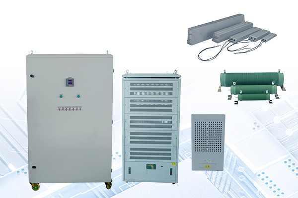
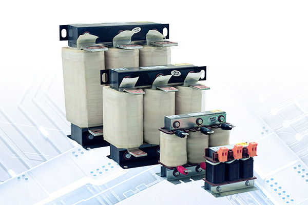
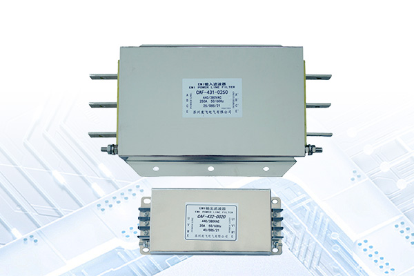
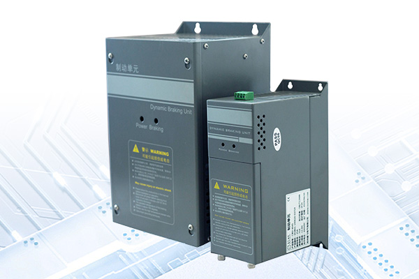
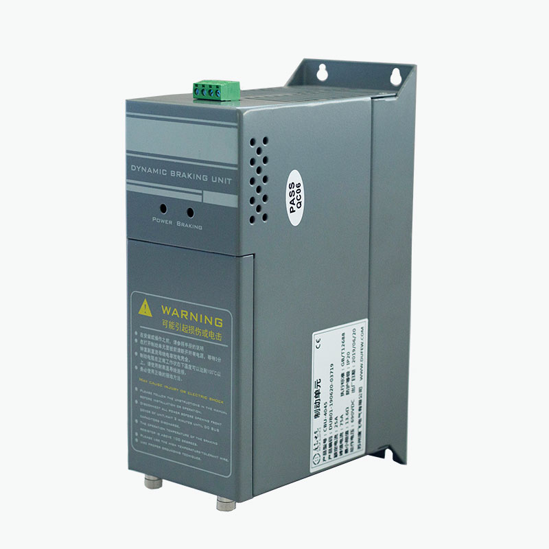
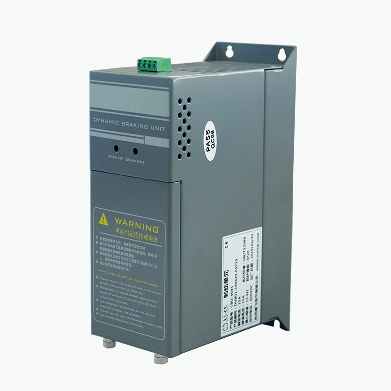
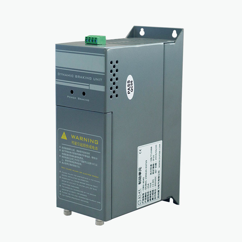
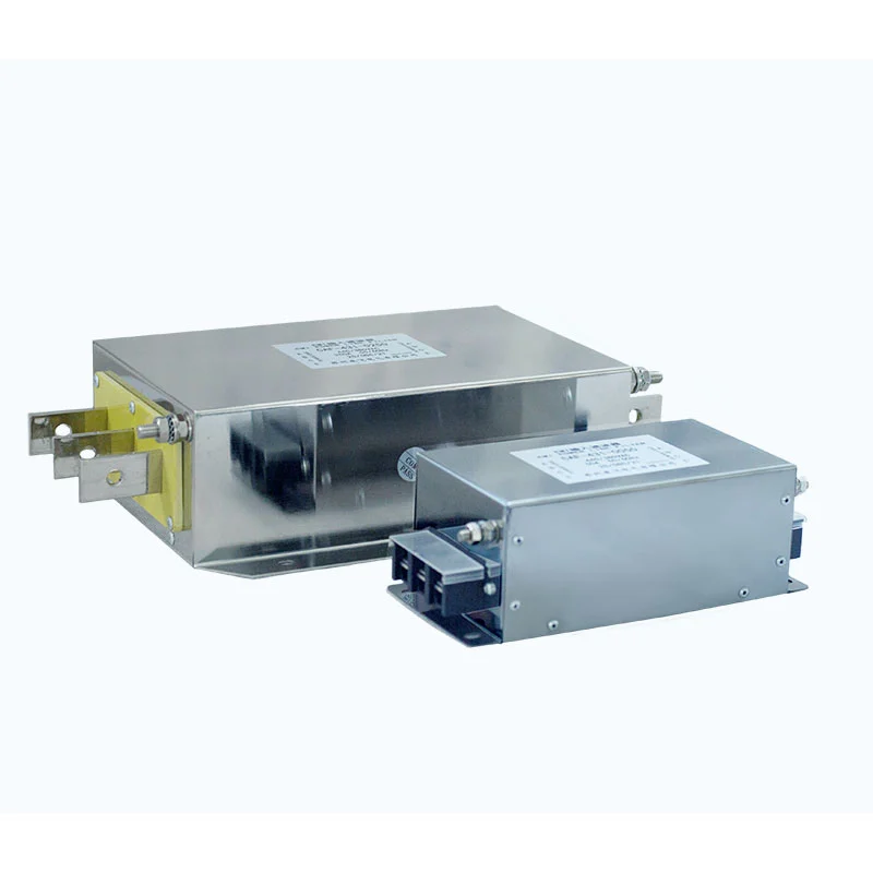
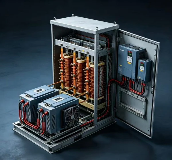
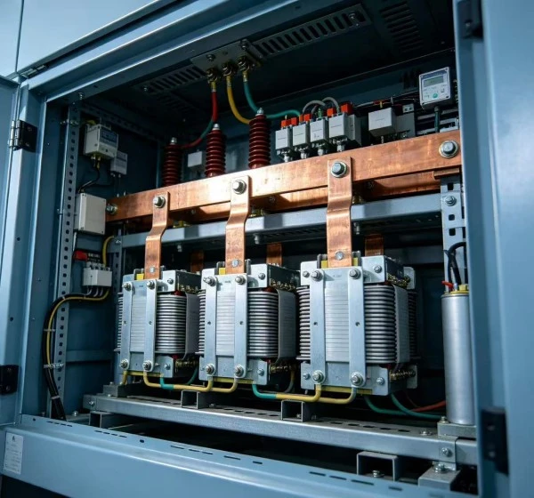
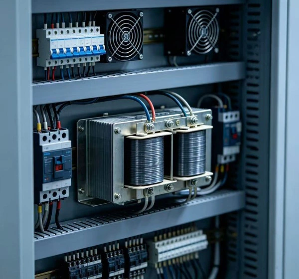
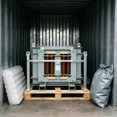
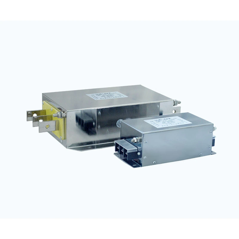
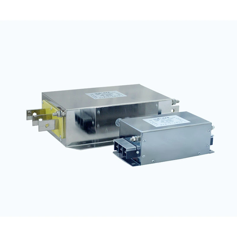
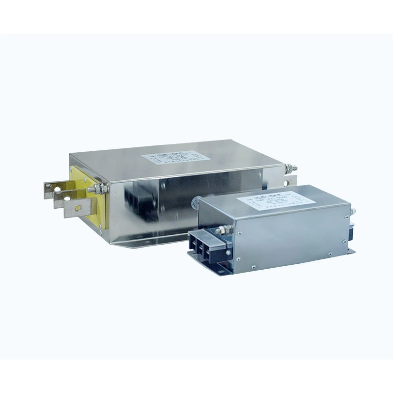
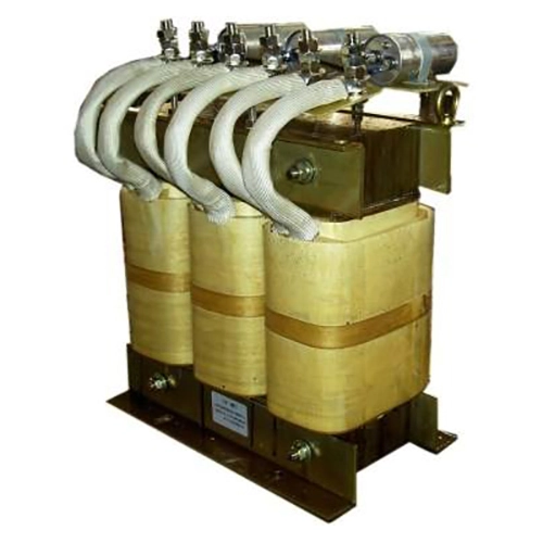
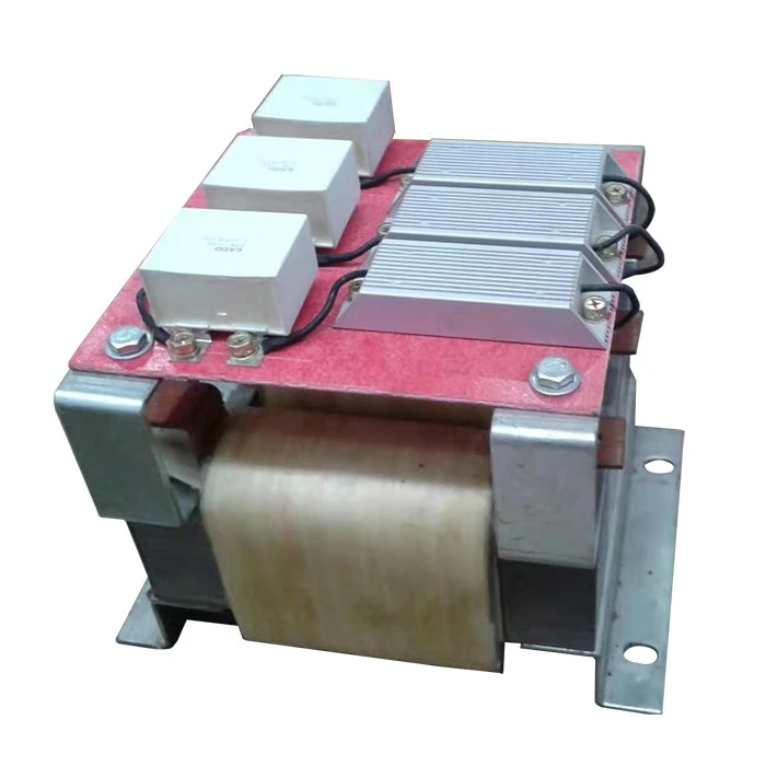
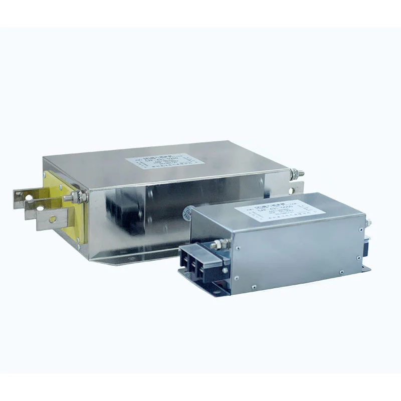
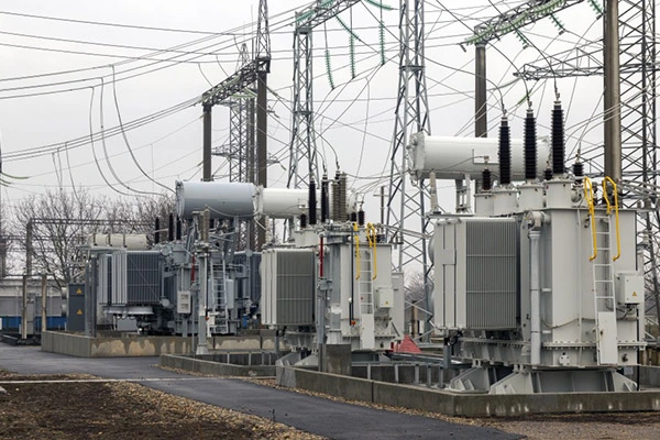
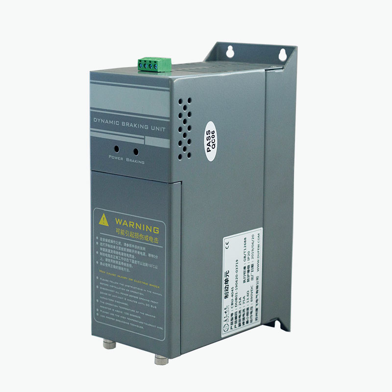
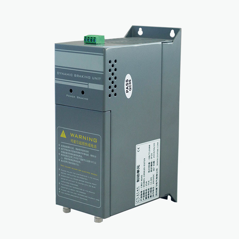
We offer a comprehensive portfolio including resistors, braking units, reactors, power filters, and transformers, with full customization options to meet diverse application requirements.
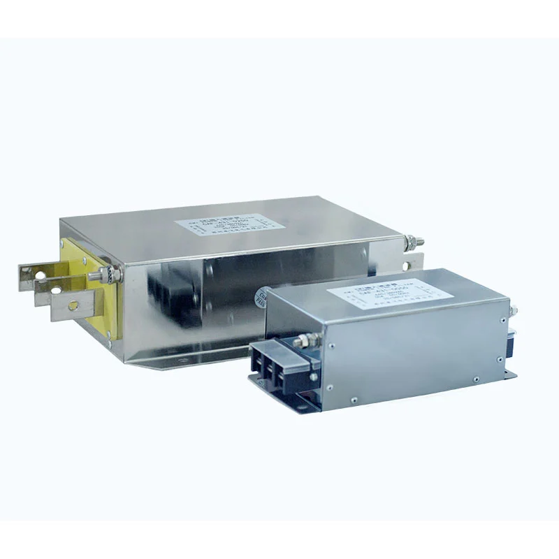
Dufew Electric Variable Frequency Drive Filter integrates input-side EMI filtering and output-side motor filtering for VFD and servo drive systems. It helps reduce conducted interference on the power side and high-frequency switching effects on the motor side, including dv/dt and reflected-wave effects. Filter ratings can be selected according to drive voltage, current, motor power, cable length, and installation conditions.
A Variable Frequency Drive Filter is installed around a variable frequency drive to control electrical interference generated during motor speed regulation.
A typical connection is:
Power Supply → Input Filtering → VFD → Output Filtering → Motor
The two sections address different parts of the drive system.
Input filtering controls conducted electromagnetic interference between the VFD and power network.
Output filtering attenuates high-frequency components produced by PWM switching before they reach the motor through the cable.
This configuration is intended for applications where both power-side EMI and motor-side high-frequency effects need to be considered.
It is different from a conventional input EMI filter, which only filters the connection between the power supply and the drive.
Input-Side EMI Filtering
Switching devices inside a VFD generate high-frequency electrical components that can travel through the power supply and affect other equipment on the same distribution system. The input section uses magnetic and capacitive components for common-mode and differential-mode attenuation, which may include common-mode chokes, differential-mode inductive components, X capacitors, Y capacitors, and resistors.
The input section is intended for conducted EMI suppression and does not replace a dedicated harmonic compensation system where specific low-frequency THD requirements apply.
Output-Side Motor Filtering
A VFD produces a PWM output waveform with rapid voltage transitions. With long motor cables, distributed capacitance and impedance can affect the voltage waveform at the motor terminals. The output section attenuates high-frequency components and can help reduce motor-side dv/dt, reflected-wave effects, motor winding insulation stress, and certain high-frequency motor noise.
Actual performance depends on the VFD switching characteristics, cable length and construction, motor insulation, grounding, and selected filter configuration.
When Is an Integrated Filter Needed?
Not every VFD installation requires both input and output filtering.
The required configuration depends on the problem being addressed.
Application Condition
Typical Filtering Consideration
VFD interference entering the power network
Input-side EMI filter
Interference affecting nearby control equipment
Input-side EMI filter
Long motor cable
Output-side filtering may be required
High motor-side dv/dt
Output-side filtering
Reflected-wave voltage concern
Output-side filtering
Both power-side and motor-side interference
Integrated input/output filter
This distinction is important during product selection. The filter should be specified according to the actual electrical problem rather than installed simply because a VFD is present.
Integrated Filter Construction
Dufew Electric combines the input and output filtering circuits within one assembly.
The two sections have separate electrical paths and terminal areas for connection to the power supply, VFD, and motor.
The filtering network can incorporate:
- Common-mode magnetic components
- Differential-mode inductive components
- X capacitors
- Y capacitors
- Damping resistors
- Other components required by the selected configuration
The integrated construction reduces the need to install two separate filter housings when both input and output filtering are required.
The actual internal arrangement depends on the product rating and configuration.
Technical Specifications
Parameter
Specification
Rated Voltage
220VAC / 380VAC / 690VAC / 1140VAC
Operating Frequency
50Hz / 60Hz / up to 500Hz
Rated Current
5A--1600A
Dielectric Strength, Line to Line
1500VDC / 60s
Dielectric Strength, Line to Ground
2500VDC / 60s
Insulation Resistance
>100MΩ at 1000VDC
Overload Capability
1.4 × rated current for 1 minute
Minimum Overload Interval
15 minutes
Maximum Cable Length*
400m shielded / 300m unshielded
Protection Grade
IP00 / IP20
Insulation Class
T40 / F (155°C)
Flame Retardant Grade
UL94V-2
Product Standard
GB/T 15287/8
* Maximum cable length is application-dependent and should be verified according to the VFD output characteristics, motor, cable type, grounding arrangement, and selected filter model.
For the integrated input/output configuration, the applicable model code should be confirmed against the corresponding product drawing and specification.
Typical Applications
Application
Main Requirement
Filtering Function
Variable Frequency Drive Systems
Control EMI generated during VFD operation
Input-side conducted EMI suppression and output-side high-frequency filtering
Servo Drive Systems
Reduce electrical interference around servo equipment
Input-side EMI control and output-side motor-side filtering
Industrial Motor Control
Improve EMC performance of motor drive systems
Suppress conducted interference and high-frequency switching components
CNC Machines & Machine Tools
Reduce interference affecting control and drive equipment
Input EMI filtering and output-side dv/dt reduction
Long Motor Cable Installations
Control reflected-wave and high-frequency voltage effects
Output-side filtering between VFD and motor
Conveyor, Pump & Fan Systems
Reduce interference from variable-speed motor operation
Input-side EMI suppression and, where required, output filtering
Industrial Automation Equipment
Limit interference between drive systems and nearby electronics
Common-mode and differential-mode filtering
Manufacturing Equipment
Address both power-side and motor-side interference
Integrated input and output filtering
Note: The required filter configuration depends on the VFD, motor, cable length, EMC conditions, and the specific interference problem. Not every VFD application requires both input and output filtering.
Selection Parameters
Selection Parameter
Information Required
Purpose
VFD Model
Manufacturer and model number
To determine the applicable input/output configuration
Rated Voltage
220VAC / 380VAC / 690VAC / 1140VAC
To match the filter voltage rating with the drive system
Rated Current
VFD input or output current
To determine the required filter current rating
Motor Power
kW or HP
To evaluate the motor-side filtering requirements
Motor Rated Voltage
Motor operating voltage
To verify output-side compatibility
Motor Cable Length
Actual cable length in meters
Important for evaluating dv/dt and reflected-wave effects
Cable Type
Shielded or unshielded; cable construction where available
EMI, motor noise, dv/dt, reflected wave, nearby equipment interference, etc.
To identify whether input filtering, output filtering, or an integrated configuration is appropriate
Grounding Arrangement
Grounding and cable shielding method
Important for effective high-frequency interference control
Recommended Information for Product Selection
For a preliminary evaluation, customers can provide:
VFD model + rated voltage + rated current + motor power + motor cable length + cable type + switching frequency + observed interference
This information is generally more useful for filter selection than specifying the filter only by motor power.
Installation Requirements
Correct installation is important because high-frequency interference can bypass part of the filtering circuit through unsuitable wiring.
Input and Output Connections
Connect the input section between the power supply and VFD.
Connect the output section between the VFD and motor.
Input and output terminals must be connected according to the product wiring diagram and must not be interchanged.
Cable Separation
Power-side and motor-side cables should be routed separately.
Avoid long parallel runs between filter input and output conductors, as electromagnetic coupling can reduce filtering effectiveness.
Grounding
The filter should be grounded according to the applicable electrical installation requirements and VFD manufacturer's EMC instructions.
For high-frequency interference, a short, low-impedance grounding path is generally preferred.
Motor Cable Shielding
Where shielded motor cable is used, the cable shield should be terminated according to the VFD manufacturer's EMC requirements.
Pre-Operation Check
Before energizing the system, verify:
- Filter voltage and current rating
- Terminal connections
- Grounding
- Input/output cable routing
- Motor connection
- Mechanical mounting
After installation, verify normal VFD and motor operation and check the original interference condition.
Manufacturing and Quality Control
Dufew Electric manufactures power electronics components including resistors, braking systems, reactors, filters, transformers, and customized electrical components. Variable Frequency Drive Filters are produced according to the required electrical configuration and application.
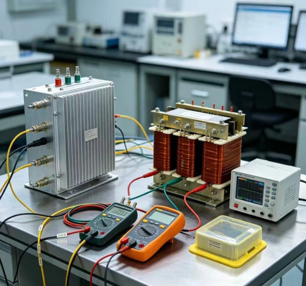
The production process typically covers component inspection, magnetic component processing, winding and insulation, filter assembly, electrical testing, final inspection, and packaging. Depending on the product configuration, quality checks may include component specification, winding, insulation, terminals, insulation resistance, dielectric strength, electrical performance, and dimensions.
Product-specific drawings, test records, and technical documents can be provided according to project requirements.
Certifications and Quality Assurance
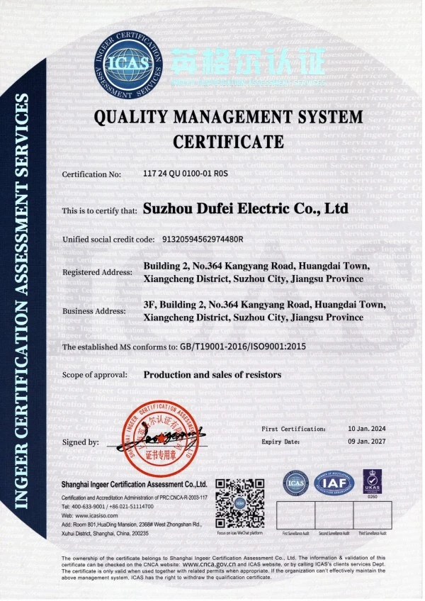
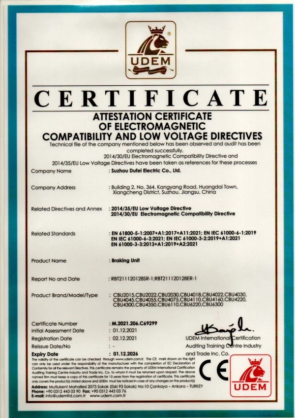
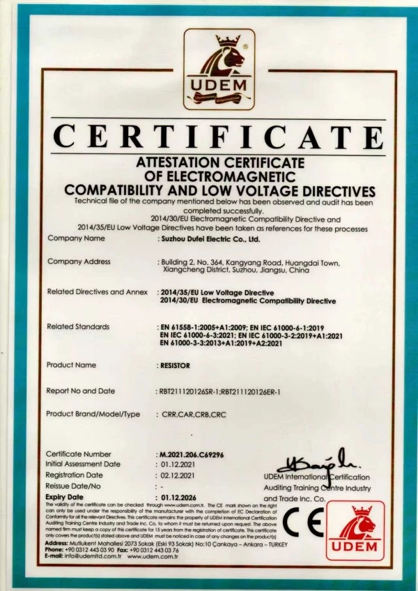
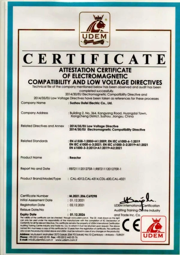
Dufew Electric has ISO and CE certifications supporting its quality management and product compliance requirements.
The applicable certificate and technical documentation should be confirmed according to the specific product model and destination market.
Quality inspection covers relevant stages from component verification and assembly through electrical testing and final inspection.
Packaging and Delivery
Dufew Electric supplies filters and other power electronics components to OEMs, distributors, system integrators, and industrial users.
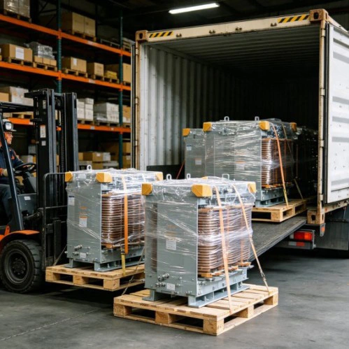
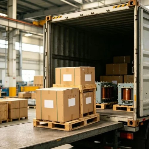
Packaging and delivery arrangements are selected according to product dimensions, weight, quantity, destination, and customer requirements.
Available shipping arrangements may include:
- Sea freight
- Air freight
- Express delivery
- Customer-nominated forwarder
Packaging is selected according to the product construction and transportation conditions.
Frequently Asked Questions
Q1: What is the difference between an input filter and an output filter?
An input filter is installed between the power supply and VFD to control conducted EMI. An output filter is installed between the VFD and motor to control high-frequency components, dv/dt, and reflected-wave effects.
Q2: Does every VFD need an output filter?
No. The requirement depends on motor cable length, VFD output characteristics, motor insulation, EMC conditions, and application requirements.
Q3: Can this filter be used with servo drives?
Yes. It can be evaluated for servo drive applications where input-side EMI or motor-side high-frequency interference needs to be controlled. The electrical rating must match the drive system.
Q4: Can the output filter reduce dv/dt at the motor?
Yes. The output section is designed to attenuate high-frequency switching components and can reduce dv/dt at the motor terminals. The actual result depends on the VFD, filter configuration, cable, and motor.
Q5: Can it be used with long motor cables?
Yes. Long motor cables can increase reflected-wave and high-frequency voltage effects, making output filtering more relevant. The allowable cable length must be confirmed for the specific application.
Q6: Does this filter replace a dedicated harmonic filter?
Not necessarily. This product is primarily intended for EMI and high-frequency filtering around VFD systems. If the requirement is to control specific power-system harmonic orders or THD, a dedicated harmonic mitigation solution should be evaluated.
Q7: Does the filter require electronic adjustment?
No electronic adjustment is normally required because the filter is passive. Correct model selection, wiring, grounding, and installation are still necessary.
Q8: What information should be provided for selection?
The VFD model, supply voltage, rated current, motor power, motor cable length, cable type, and the specific interference or motor-side issue are useful for selecting the appropriate configuration.
Variable Frequency Drive Filter Manufacturer in China
Dufew Electric manufactures Variable Frequency Drive Filters for VFDs, servo drives, motor control systems, and industrial automation equipment.
The integrated configuration provides input-side EMI filtering and output-side motor filtering within one assembly. Selection can be based on drive rating, motor characteristics, cable length, EMC conditions, and installation requirements.
For product evaluation, provide the VFD model, motor power, rated current, motor cable length, cable type, and supply voltage.
Hot Tags: Variable Frequency Drive Filter, VFD Filter, EMI Filter for VFD
Looking for reliable power electronics components? Contact Dufew Electric, a professional manufacturer and supplier in China, for customized resistors, braking systems, reactors, transformers, and power solutions tailored to your industrial applications.
We use cookies to offer you a better browsing experience, analyze site traffic and personalize content. By using this site, you agree to our use of cookies.Privacy Policy