English


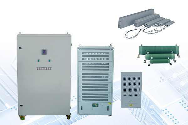
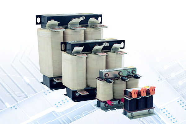
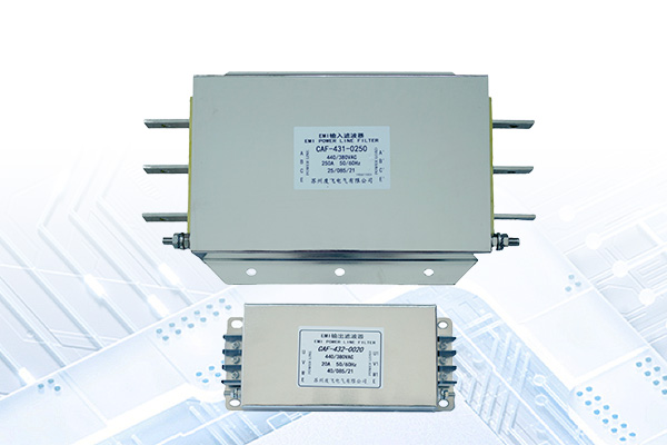
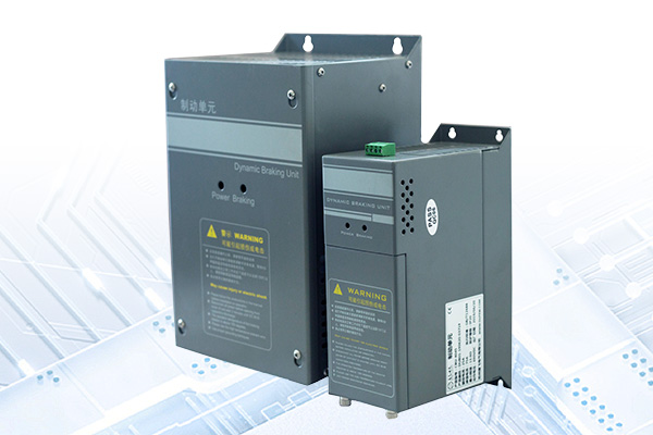
We offer a comprehensive portfolio including resistors, braking units, reactors, power filters, and transformers, with full customization options to meet diverse application requirements.
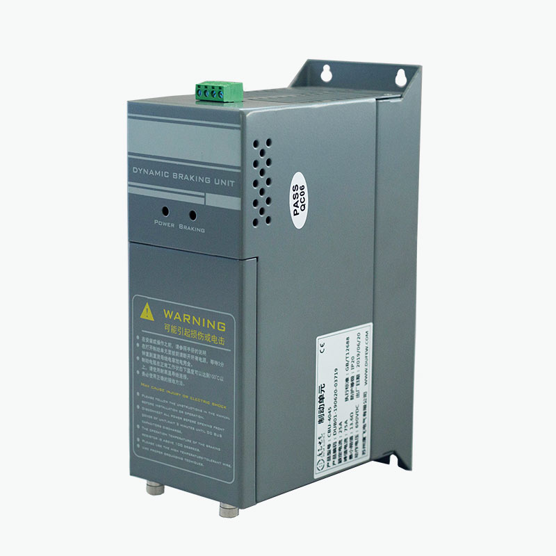
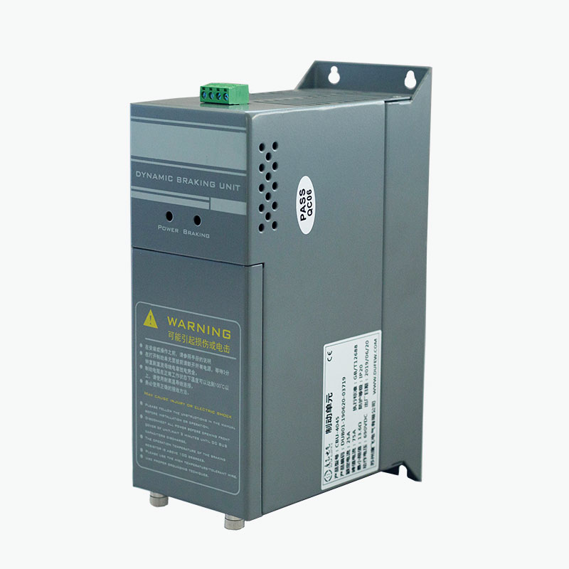
A braking chopper is the switching component of a dynamic braking system. It does not dissipate regenerative energy by itself; instead, it controls the connection between the DC bus and braking resistor.
During motor deceleration, the motor can operate temporarily as a generator. The resulting regenerative energy flows back to the DC bus and causes the bus voltage to increase. When the voltage reaches the chopper's operating threshold, the IGBT switching circuit conducts and directs the energy to the braking resistor.
When the DC bus voltage falls below the release threshold, the chopper switches off.
This operating cycle allows the braking resistor to absorb regenerative energy and helps prevent excessive DC bus voltage during deceleration or overhauling operation.
- Controls the discharge of regenerative energy through the braking resistor
- Limits DC bus voltage rise during dynamic braking
- Provides rapid switching during regenerative conditions
- Supports external braking for drives requiring higher braking capacity
- Provides protection for the chopper and braking circuit
- Allows multiple units to be connected in parallel for higher braking requirements
The actual braking performance depends on the drive system, motor inertia, load characteristics, braking resistor, braking frequency, and required deceleration time.
The CBU Series uses an IGBT-based switching circuit connected to the DC bus of the variable frequency drive.
The operating sequence is:
Motor Deceleration → Regenerative Energy → DC Bus Voltage Rise → Chopper Turns On → Energy Flows to Braking Resistor → Energy Dissipated as Heat
The chopper continuously monitors the DC bus voltage rather than relying on a separate external controller.
When the bus voltage exceeds the configured operating threshold, the IGBT conducts and transfers regenerative energy to the resistor. When the voltage returns to the appropriate range, the switching device turns off.
This control method is particularly useful for applications in which the regenerated energy is too large or too frequent for the drive's internal braking circuit.
| Parameter | Specification |
|---|---|
| System Voltage | 220VAC / 380VAC / 690VAC |
| Braking Voltage for 220V System | DC340 / 360 / 380 / 400 / 420V ±10V |
| Braking Voltage for 380V System | DC630 / 660 / 690 / 730 / 760V ±10V |
| Braking Voltage for 690V System | DC1140V ±10V |
| Control Method | Automatic DC bus voltage monitoring |
| Hysteresis | ≤10V |
| Parallel Response | ≤1ms |
| Fan Start Temperature | Approx. 45°C |
| Overtemperature Protection | Approx. 85°C |
| Fault Output | Relay contact: 0.6A/250VAC, 2A/30VDC |
| Protection Rating | IP20 or higher |
| Flame Retardant Grade | UL94 V-2 |
| Applicable Standard | GB/T 12668 |
Note: The final braking voltage, model, and electrical configuration should be confirmed according to the selected product and drive system.
The CBU Series integrates the switching and protection functions required for an external dynamic braking circuit.
The control circuit continuously monitors the DC bus voltage. When the voltage reaches the configured braking threshold, the IGBT switching circuit conducts to transfer regenerative energy to the braking resistor.
The chopper responds to changes in DC bus voltage without requiring an external control system. For parallel configurations, the specified synchronization response is within 1ms.
Different braking voltage levels are available for 220V, 380V, and 690V drive systems. The appropriate setting is determined by the drive's DC bus voltage and the selected CBU model.
Depending on the product configuration, protection functions include:
- DC bus overvoltage protection
- Braking circuit short-circuit protection
- Overtemperature protection
- Fan fault protection
- Fault relay output
Protection conditions can disable the braking output and provide a fault signal to the external control system.
The CBU Series uses forced-air cooling for applications requiring higher braking frequency or power.
The cooling fan starts at approximately 45°C module temperature, while the specified overtemperature protection point is approximately 85°C.
Actual thermal performance depends on:
- Braking power
- Braking duty cycle
- Ambient temperature
- Cabinet ventilation
- Installation clearance
- Operating frequency
The chopper should be installed with sufficient ventilation and clearance according to the product installation requirements.
| Code | Description |
|---|---|
| CBU | Dufew Electric braking chopper series |
| 4 | Voltage class: 4 = 380V |
| 030 | Model designation according to the product series |
The model should be selected according to the drive voltage, required braking capacity, braking duty cycle, braking resistor, and load characteristics.
Braking chopper selection should be based on the actual regenerative conditions of the drive system rather than motor power alone.
| Selection Parameter | Engineering Consideration |
|---|---|
| Drive System Voltage | Determines the applicable DC bus voltage range |
| Motor Power | Provides a reference for the overall braking system size |
| Load Type | Hoisting, elevator, conveyor, centrifuge, and other loads have different regenerative characteristics |
| Load Inertia | Higher inertia generally produces more regenerative energy during deceleration |
| Deceleration Time | Shorter deceleration increases the instantaneous braking power requirement |
| Braking Frequency | Frequent braking increases thermal loading |
| Required Braking Power | Determines the required chopper and resistor capacity |
| Braking Resistor | Resistance value and power rating must match the braking circuit |
| Duty Cycle | Determines continuous and intermittent thermal requirements |
| Ambient Temperature | Influences heat dissipation and allowable operating conditions |
| Installation Conditions | Cabinet size, ventilation, and clearance affect thermal performance |
| Parallel Operation | Multiple units may be used when one chopper is insufficient for the required braking capacity |
For engineering selection, the drive model, motor power, load type, deceleration time, braking frequency, and existing braking resistor specifications should be provided where available.
| Application | Braking Requirement |
|---|---|
| Elevators | Controls regenerative energy during downward travel and rapid deceleration |
| Hoisting Equipment | Handles regenerative energy generated when lowering loads |
| Cranes | Supports controlled deceleration of high-inertia and lifting loads |
| Centrifuges | Dissipates regenerative energy during rapid deceleration |
| Industrial Washing Machines | Suitable for systems with repeated acceleration and deceleration |
| Textile Machinery | Supports frequent braking cycles |
| Paper Machinery | Used where drive systems require controlled dynamic braking |
| Machine Tools | Helps manage regenerative energy during rapid stopping |
| Conveyor Systems | Applicable where load inertia produces DC bus voltage rise |
| Other VFD Systems | Suitable when the internal braking capacity of the drive is insufficient |
The chopper should be selected according to the actual braking energy and duty cycle rather than motor power alone.
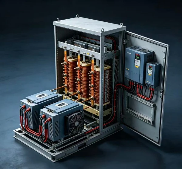
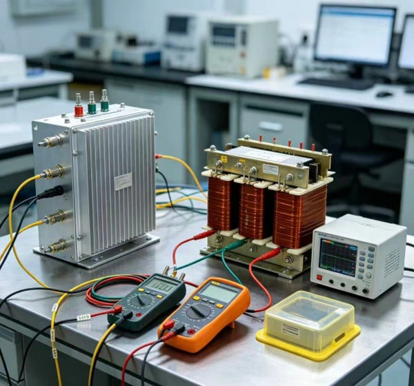
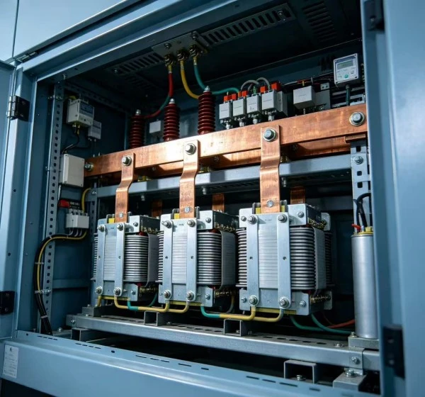
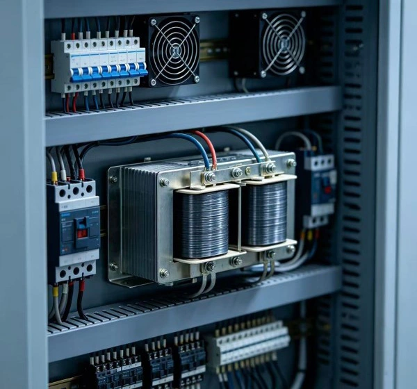
A braking chopper and braking resistor perform different functions and are normally used together.
| Component | Function |
|---|---|
| Braking Chopper | Controls when regenerative energy is transferred from the DC bus |
| Braking Resistor | Converts the transferred electrical energy into heat |
| DC Bus | Provides the electrical path between the drive and braking circuit |
The chopper controls the switching process, while the resistor absorbs the energy. Therefore, the resistance value, power rating, and duty cycle of the resistor must be compatible with the chopper and drive.
Multiple CBU units can be connected in parallel when the required braking capacity exceeds the capacity of a single unit. The parallel configuration uses the corresponding control interface to coordinate switching operation between the connected units and distribute the braking load according to the system design.
When configuring multiple units, factors such as total braking power, DC bus voltage, number of choppers, braking resistor configuration, wiring arrangement, braking duty cycle, and thermal conditions should be considered. The number of CBU units and the appropriate connection method should be confirmed according to the selected model, system parameters, and application requirements.
The braking chopper is connected to the variable frequency drive's DC bus and braking resistor according to the specified wiring diagram.
Before commissioning:
1. Confirm that the CBU voltage class matches the drive system.
2. Verify the DC bus polarity.
3. Confirm the braking resistor resistance and power rating.
4. Check that all terminals are correctly connected and tightened.
5. Provide adequate ventilation around the chopper.
6. Keep power and control wiring appropriately separated.
7. Connect the fault relay circuit where required.
8. Complete electrical inspection before energizing the system.
Installation should be performed by qualified electrical personnel in accordance with the product documentation and applicable electrical requirements.
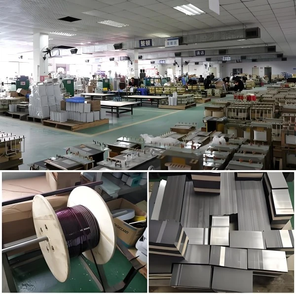
Dufew Electric manufactures power electronics components for industrial drive and power control applications, including braking resistors, braking units, reactors, filters, transformers, and related electrical components. The production process covers key stages from incoming material inspection and component assembly to electrical testing, protection function verification, final inspection, and packaging.
Depending on the product configuration, quality inspection may include electrical connection inspection, insulation resistance testing, dielectric strength testing, switching function verification, protection function verification, cooling fan inspection, terminal inspection, and dimensional inspection. These procedures are applied according to the product design and applicable technical requirements.
Product-specific technical documents and test records can be provided according to project requirements to support product evaluation, quality verification, and system integration.
The CBU Series is manufactured according to the applicable requirements of GB/T 12668. Dufew Electric also maintains relevant ISO and CE certifications within its quality and product compliance system.
Applicable certification and technical documents should be confirmed according to the specific model and order.
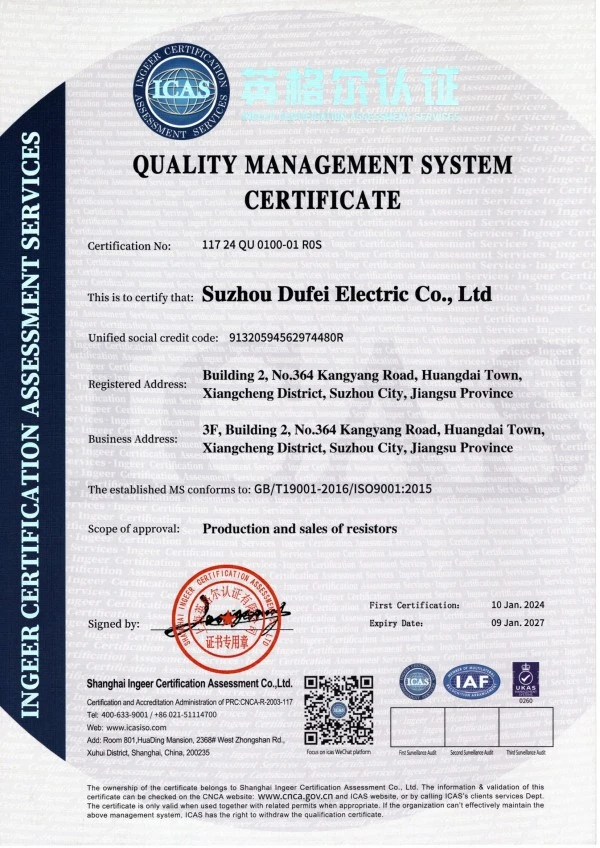
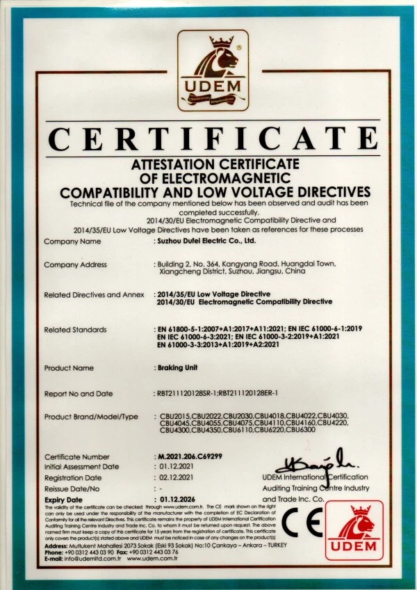
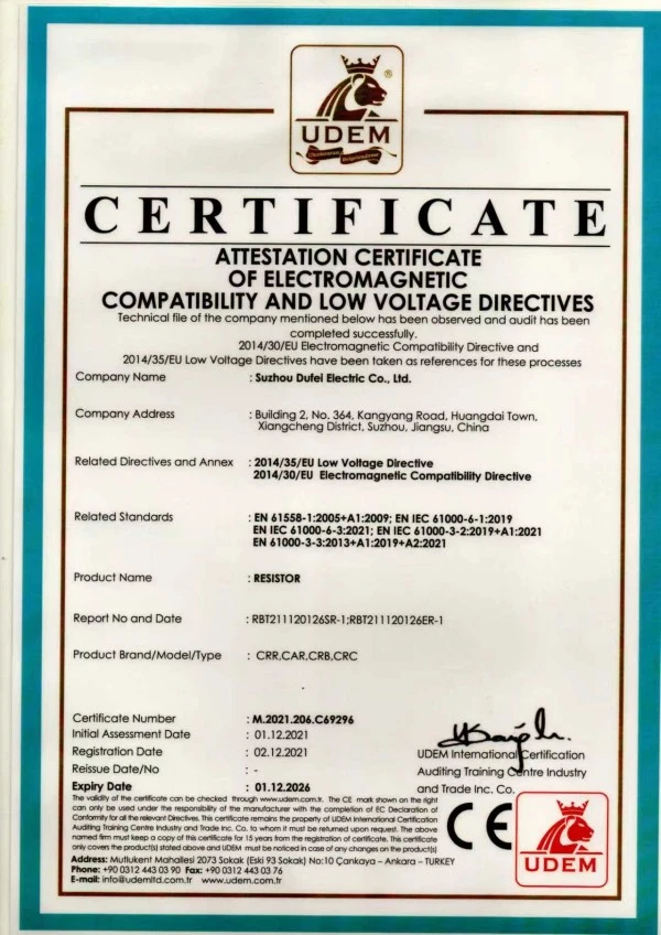
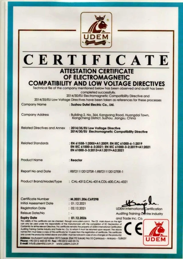
Dufew Electric manufactures power electronics components for industrial drives, power control, and power quality applications. Its product portfolio covers braking, resistor, reactor, filter, and transformer solutions, including Braking Resistors, Braking Choppers, Braking Units, Input & Output Reactors, DC Reactors, EMI Filters, dv/dt Filters, Sine Wave Filters, Harmonic Filters, Transformers, and Industrial Resistors.
For projects requiring multiple electrical components, Dufew Electric can coordinate related product specifications according to the application, electrical ratings, installation conditions, and system requirements.
Product selection considers DC bus voltage, braking power, load characteristics, braking frequency, resistor specifications, and duty cycle.
Dufew Electric's product range covers braking, resistor, reactor, filter, and transformer applications for industrial electrical systems.
Electrical ratings, braking voltage, dimensions, cooling arrangements, and parallel configurations can be evaluated according to project requirements.
Manufacturing includes component inspection, assembly control, electrical testing, protection-function verification, and final inspection.
It monitors the DC bus voltage of a variable frequency drive and switches the braking circuit when regenerative energy causes the voltage to rise. The regenerative energy is then transferred to a braking resistor for dissipation.
The chopper controls when the braking circuit is switched on and off. The resistor absorbs the transferred electrical energy and converts it into heat. The two components work together in a dynamic braking system.
An external unit may be necessary when the drive's built-in braking capacity cannot handle the required regenerative energy, particularly with short deceleration times, high-inertia loads, frequent braking, or overhauling loads.
Yes, provided the drive has compatible DC bus terminals and voltage characteristics. The electrical specifications should be checked before connection rather than selecting solely by motor power.
Yes. Multiple units can be used when the required braking capacity exceeds the rating of one unit. The number of units, resistor arrangement, wiring, and control configuration should be determined from the required braking duty.
The resistance value and power rating should be determined from the DC bus voltage, required braking power, braking energy, braking frequency, and duty cycle. The resistor must also comply with the drive and braking circuit requirements.
No software commissioning is normally required because the switching operation is controlled automatically by DC bus voltage. Before operation, wiring, polarity, resistor specifications, cooling, protection connections, and insulation should be checked.
Provide the drive model, system voltage, motor power, load type, deceleration time, braking frequency, load characteristics, braking resistor specifications, and installation conditions. These parameters can be used to determine the appropriate electrical configuration.
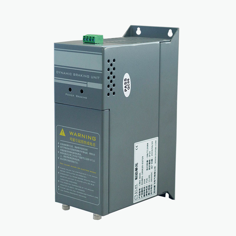
Dufew Electric CBU Series Braking Choppers are used in variable frequency drive systems to control regenerative energy during deceleration, lowering, and other overhauling conditions.
Selection should consider DC bus voltage, braking power, braking resistor characteristics, duty cycle, load conditions, and installation requirements. Dufew Electric also supplies braking resistors and related power electronics components for industrial drive systems.
For product selection, customers can provide the drive voltage, motor power, load type, deceleration time, braking frequency, and braking resistor specifications.
Address
No. 364, Kangyang Road, Huangdai Town, Xiangcheng District, Suzhou City, Jiangsu Province, China
Tel