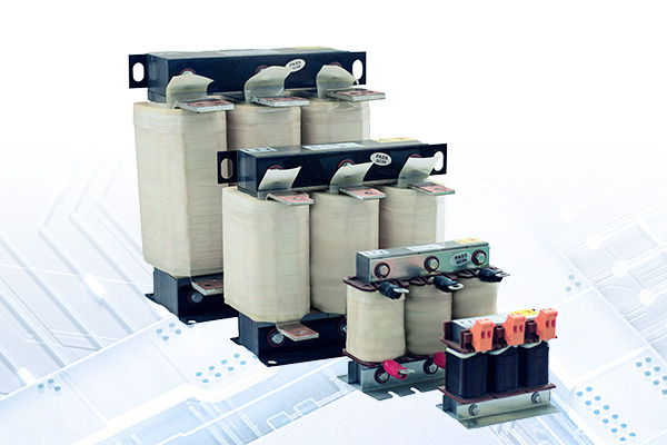
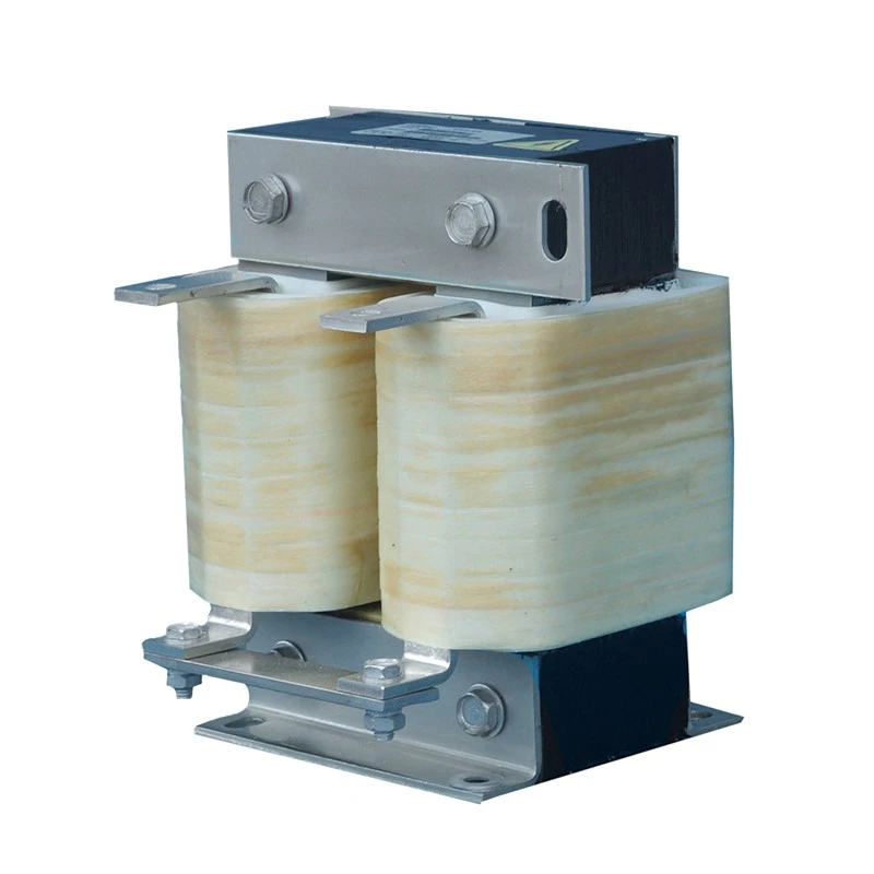
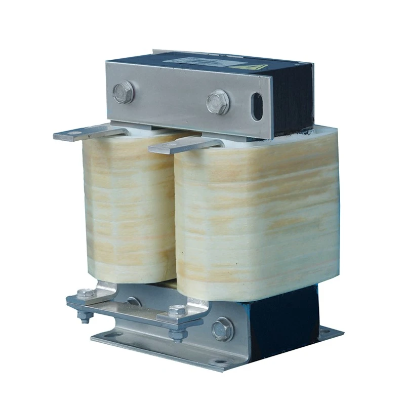
In a variable frequency drive, the rectifier converts incoming AC power into DC power before the inverter produces the variable output required by the motor. Between these stages, the DC link needs to handle pulsating current and changes in load demand. A properly selected DC Reactor adds inductive impedance to this section of the circuit, helping control current ripple and reduce the electrical stress placed on the DC bus and associated components.
The effect is mainly electrical rather than mechanical. It does not control motor speed or dissipate regenerative energy. Its purpose is to influence how current behaves within the intermediate DC circuit, making it an important consideration in certain drive architectures and power-conversion systems.
Role in the DC Link
A conventional AC drive first rectifies the incoming supply and then stores energy in the DC link before the inverter stage. The capacitors in this section smooth the DC voltage, while the current flowing through the link is affected by the rectifier and load conditions.
Without sufficient impedance, the charging and pulsating characteristics of the rectifier can produce relatively high current peaks. Adding inductance changes this current path and helps limit rapid variations before they reach the DC-link capacitors.
This can be particularly relevant in drives where the DC bus is exposed to substantial ripple current or where the incoming power network has demanding operating conditions.
What Does It Help Control?
|
Electrical Condition
|
Role of the Inductive Component
|
|
DC-link current ripple
|
Limits rapid changes in current
|
|
Rectifier current peaks
|
Provides additional impedance in the DC path
|
|
Harmonic current
|
Can contribute to harmonic reduction in suitable drive designs
|
|
Capacitor current stress
|
Helps reduce the ripple current imposed on DC-link capacitors
|
|
DC bus fluctuations
|
Supports a more controlled current waveform
|
The actual effect depends on the rectifier topology, drive design, capacitance, supply characteristics, and operating load. It should therefore be selected as part of the complete DC-link design rather than treated as an independent add-on.
Why DC-Link Ripple Matters
DC-link capacitors are exposed to ripple current during normal drive operation. Excessive ripple contributes to internal heating, and temperature is an important factor in capacitor service life.
Additional inductance can reduce the magnitude of current fluctuations reaching the capacitor bank. Schneider Electric documentation, for example, notes that line-side inductance can reduce DC-bus ripple current and the current stress experienced by the main capacitors. :contentReference[oaicite:0]{index=0}
This is one reason inductive impedance is considered in drive designs where capacitor loading, harmonic current, or power-network conditions require closer control.
Applications in Variable Frequency Drives
The most common application is within AC drive systems using a rectifier, DC link, and inverter. It may also be considered in other power-conversion equipment where an intermediate DC circuit carries substantial pulsating current.
Typical equipment includes industrial motor drives, pumps, fans, compressors, conveyors, machine tools, HVAC equipment, and other variable-speed machinery.
The requirement is not determined by motor power alone. Drive topology, supply impedance, DC-link design, load profile, and harmonic conditions can all influence the specification.
DC Reactor vs. AC Reactor
The two components are closely related, but their installation positions are different.
An AC Reactor is connected in an AC circuit, commonly on the line side or motor side of a drive. A DC-link version is placed in the intermediate DC circuit after rectification.
|
Item
|
AC-Side Configuration
|
DC-Link Configuration
|
|
Electrical section
|
AC supply or motor circuit
|
Intermediate DC circuit
|
|
Main consideration
|
AC current and voltage conditions
|
DC-link current and ripple
|
|
Typical application
|
Line-side or motor-side drive protection
|
DC bus current control and harmonic mitigation
|
Some drives use an AC line reactor, a DC-link component, or built-in impedance depending on the manufacturer's design. ABB and Schneider Electric both document the use of inductive impedance as one approach to managing harmonic current in conventional drive systems. :contentReference[oaicite:1]{index=1}
How to Select the Right Specification
Selection starts with the electrical conditions inside the drive, not simply the motor's rated power.
Key information normally includes DC voltage, continuous current, overload current, inductance, operating frequency, ambient temperature, installation position, insulation requirements, and available space. The expected current waveform and duty cycle should also be considered where the equipment operates under changing loads.
Thermal performance is equally important. Copper losses, core losses, enclosure conditions, and surrounding temperature all influence the operating temperature of the component. Adequate cooling and appropriate derating should be considered when the equipment will operate continuously at a high load.
Relationship with Other Power Components
A drive system may contain several power electronics components, but their functions are not interchangeable.
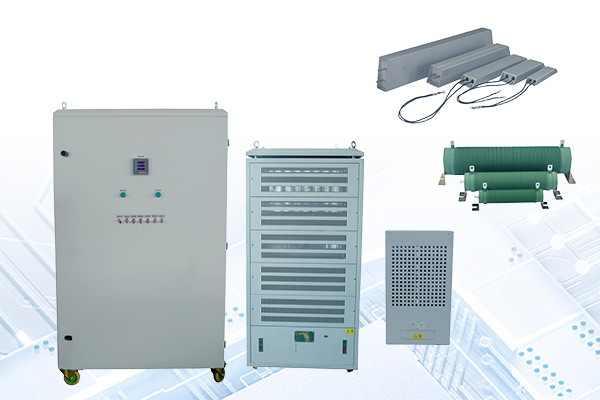
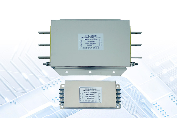
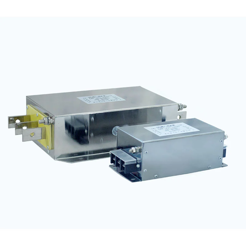
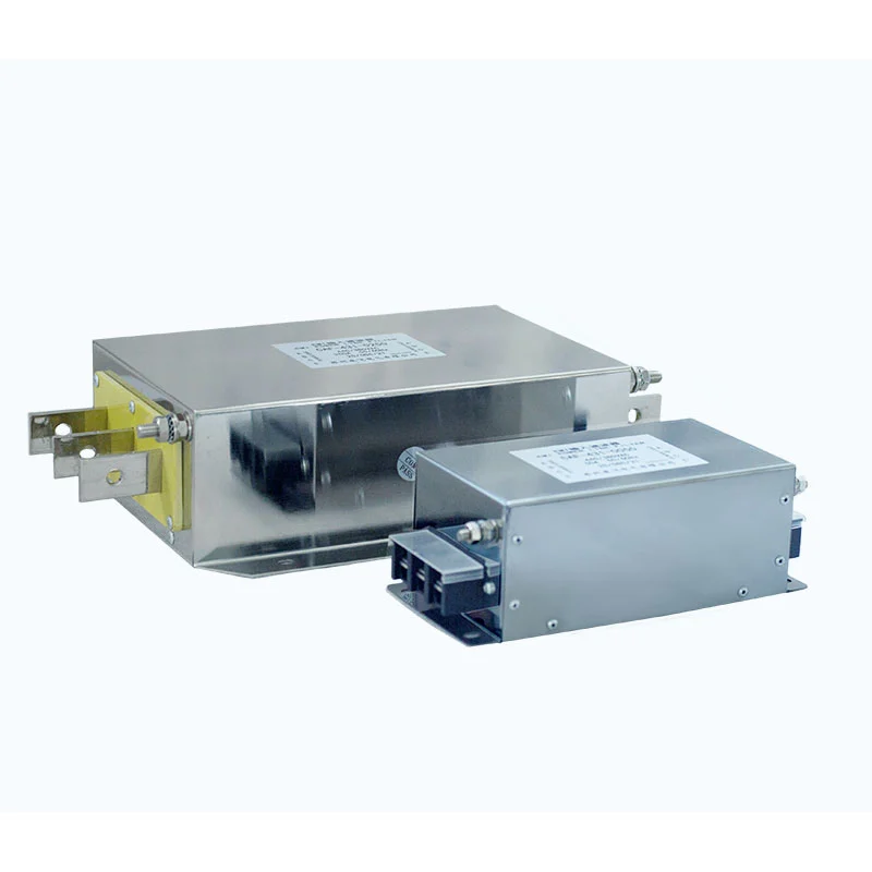
A Resistor is generally selected for current limitation or energy dissipation. A Filter targets unwanted frequency components or electromagnetic interference according to its circuit position and construction.
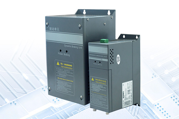
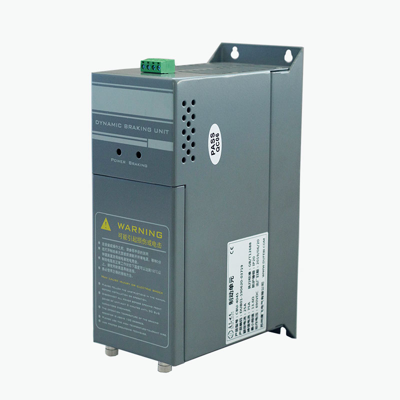
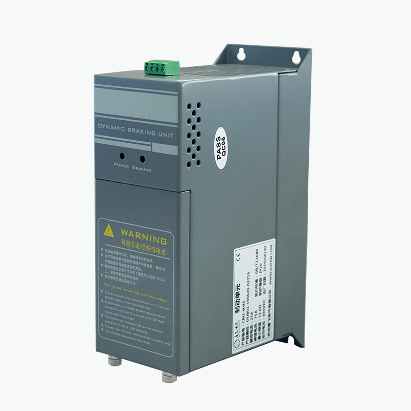
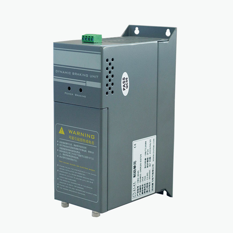
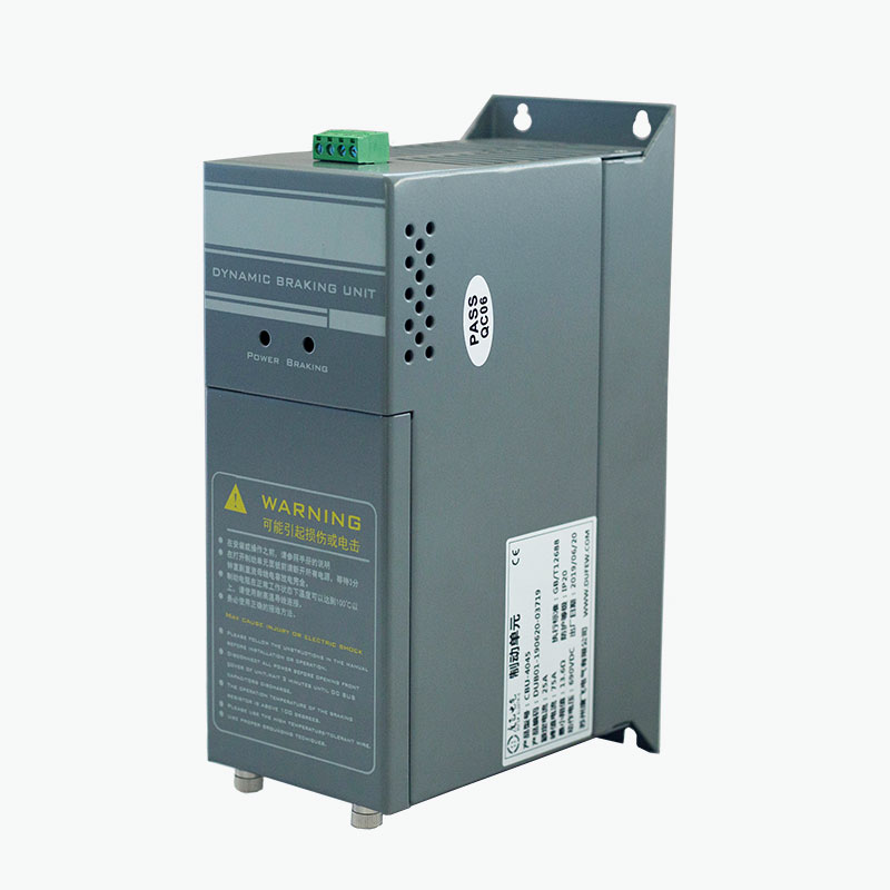
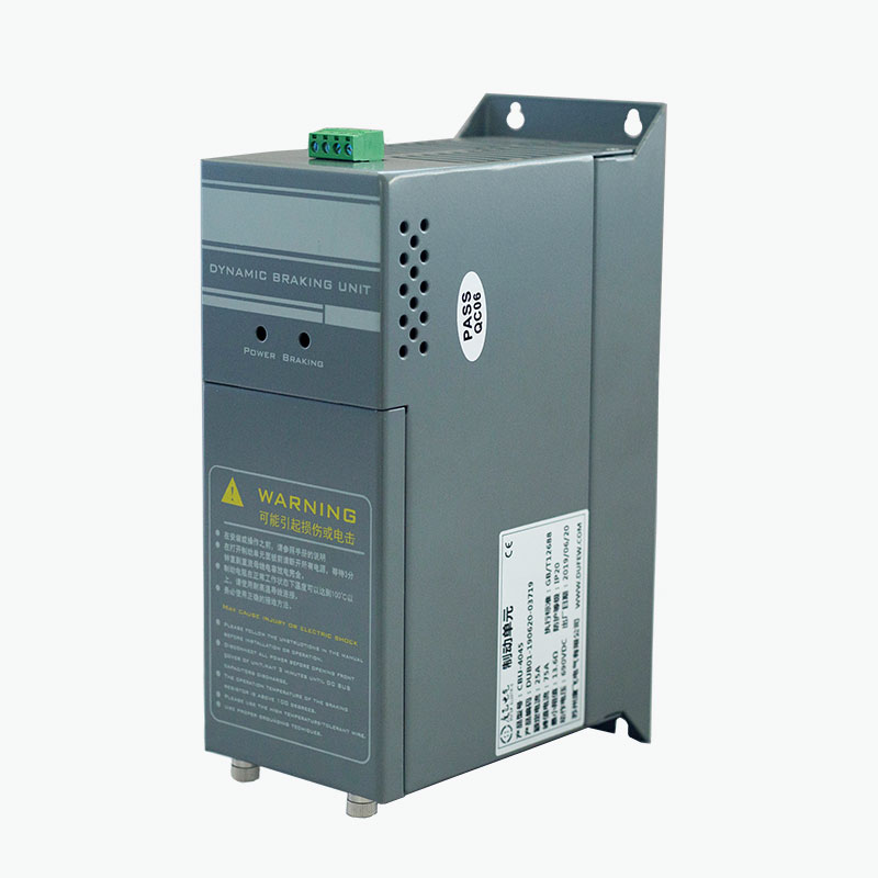
A Braking Unit has another purpose: it controls regenerated energy during motor deceleration and normally works together with a braking resistor. The inductive component discussed here remains part of the DC-link power path.
Understanding these differences helps engineers avoid selecting a component simply because several products appear in the same drive cabinet.
Engineering Considerations for OEM Projects
For an equipment manufacturer, the available installation space can be as important as the electrical rating. Mounting dimensions, terminal position, insulation clearance, cooling method, connection structure, and enclosure arrangement may need to match the existing drive design.
Dufew Electric can evaluate these requirements according to the actual application. Technical information such as DC voltage, rated current, overload conditions, inductance, operating cycle, ambient temperature, and mechanical dimensions provides a useful basis for product selection.
This is particularly relevant when replacing an existing component or developing a drive cabinet around a specific electrical architecture.
Dufew Electric for Power Electronics Components
Dufew Electric manufactures electrical components for motor drives, industrial automation, renewable energy equipment, and power-control systems. Its product range covers inductive, resistive, filtering, and braking applications.
As a China manufacturer and supplier, the company works with OEM equipment manufacturers, distributors, system integrators, and industrial users. Standardized production and quality inspection are applied to support consistent electrical and mechanical specifications, with ISO and CE certifications available for relevant products and requirements.
FAQ
Q1: What is the main purpose of a DC-link reactor?
It adds inductive impedance to the DC circuit of a power converter or drive. Its main functions can include limiting current ripple, reducing current peaks, and lowering the ripple-current stress placed on DC-link capacitors.
Q2: Does it reduce harmonics?
It can contribute to harmonic-current reduction in suitable drive configurations. The actual result depends on the rectifier, drive architecture, impedance value, supply conditions, and other components in the system.
Q3: Is it the same as an AC line reactor?
No. An AC line reactor operates in the AC section of the circuit, while a DC-link version is installed after rectification. Their electrical conditions and selection parameters are therefore different.
Q4: Does every VFD require one?
No. Some drives already include sufficient DC-link impedance, while others may use an AC-side reactor or another harmonic-mitigation method. The requirement should be determined from the drive design and operating conditions.
Q5: What information is needed when requesting a quotation?
Useful details include DC voltage, rated and overload current, required inductance, operating conditions, ambient temperature, installation dimensions, connection method, and quantity. The drive model and application can also help confirm the appropriate specification.