‌Suzhou Dufew Electrical Co., Ltd.‌
Products
Products

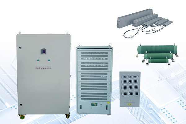
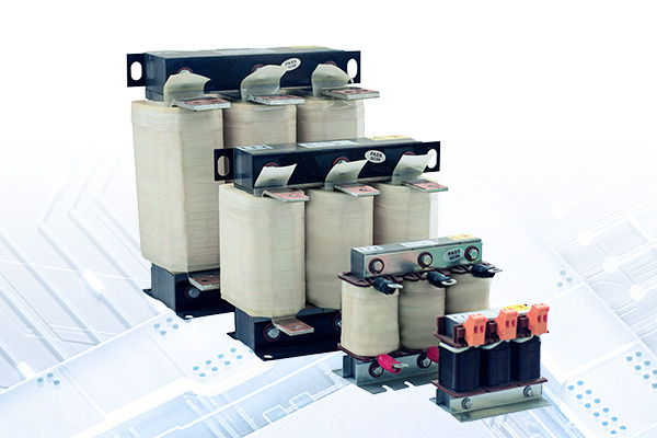
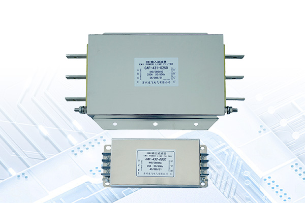
We offer a comprehensive portfolio including resistors, braking units, reactors, power filters, and transformers, with full customization options to meet diverse application requirements.

Braking Module
  • Braking ModuleBraking Module

Braking Module

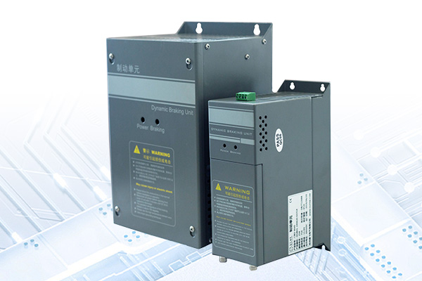
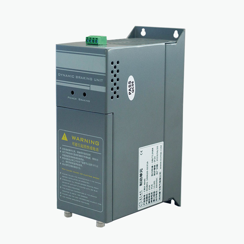
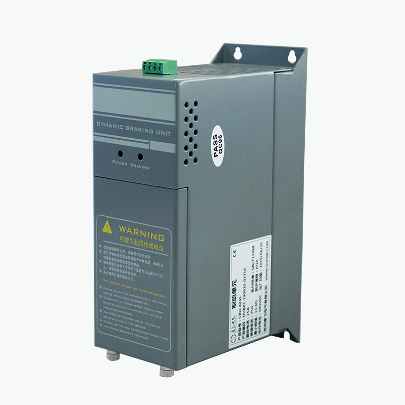
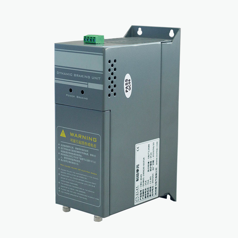
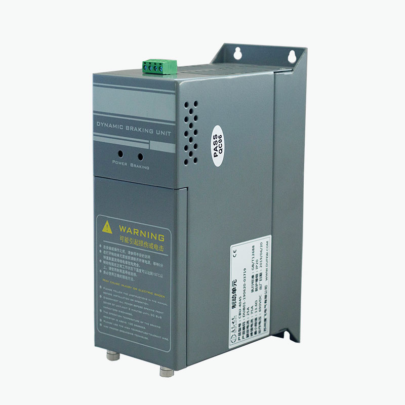
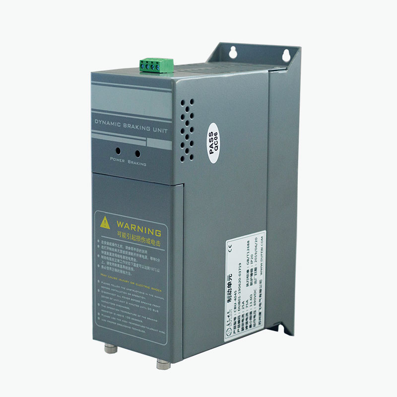
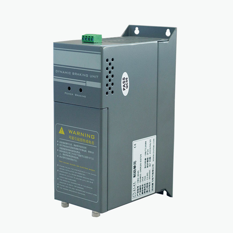
Dufew Electric CBU Series Braking Module is an IGBT-based dynamic braking component for variable frequency drive systems. It is connected to the DC bus and works with an external braking resistor to dissipate regenerative energy generated during motor deceleration or overhauling operation. Its integrated board-level construction combines the braking circuit, control, temperature monitoring, and fault output in one module for installation inside VFD control cabinets.

A braking module is used when a variable frequency drive needs additional dynamic braking capacity. It provides a controlled electrical path for regenerative energy when the DC-bus voltage rises during braking.

The CBU Series is connected between the VFD DC bus and an external braking resistor. The module monitors the DC-bus voltage and controls the IGBT switching circuit according to the configured braking threshold.

Unlike a regenerative drive system, the braking circuit does not return energy to the utility grid. Instead, the regenerative energy is transferred to the braking resistor and converted into heat.

This configuration is applicable to drive systems where the VFD's built-in braking capacity is insufficient or where an external braking circuit is required.

Braking Module

How the Braking Circuit Works

During normal motor operation, electrical energy is supplied from the VFD to the motor. During rapid deceleration or overhauling operation, the direction of energy flow can reverse and the motor temporarily operates as a generator.

The regenerative energy is then returned to the VFD's DC bus, causing the bus voltage to increase.

The CBU Series responds to this voltage change through the following sequence:

DC-Bus Voltage Rises → IGBT Turns On → Braking Resistor Receives Regenerative Energy → Energy Is Converted to Heat → DC-Bus Voltage Falls → IGBT Turns Off

The IGBT therefore functions as an electronically controlled switch between the DC bus and braking resistor.

The switching threshold determines when the braking circuit becomes active, while the resistor determines how much regenerative energy can be dissipated. Both the module and resistor must therefore be selected according to the drive voltage, braking power, braking frequency, and duty cycle.

Module Construction

The CBU Series uses an integrated board-level design. The main braking and monitoring functions are incorporated into the module rather than distributed among several separate control components.

The module incorporates:

- IGBT power switching circuit

- DC bus voltage detection

- Braking control circuit

- Temperature monitoring

- Cooling fan control

- Fault protection

- Relay fault output

- DC bus and braking resistor terminals

The structure is intended for direct integration into suitable VFD control cabinets.

The external braking resistor remains a separate component because it is responsible for converting the regenerative electrical energy into heat.

Key Technical Features

IGBT-Based Switching

The braking circuit uses an IGBT as the main switching device. The switching state is controlled according to DC-bus voltage rather than by mechanical switching components.

Integrated Temperature Monitoring

The module monitors operating temperature and controls the cooling fan according to the specified temperature thresholds. The CBU Series starts the fan at approximately 45°C module temperature and provides over-temperature protection at approximately 85°C, according to the product configuration.

Parallel Operation

Multiple modules can be connected in parallel when the required braking capacity exceeds the capacity of a single unit. A synchronization interface is provided for coordinated operation.

Adjustable Braking Voltage

The braking threshold can be configured for different DC-bus voltage conditions. For a 380 VAC system, the factory setting is DC690V, with other switching levels available according to the specified configuration.

Hardware Protection

The module incorporates protection functions for conditions such as overvoltage, overcurrent, short circuit, and over-temperature. A relay output is available for external fault monitoring.

Board-Level Installation

The braking circuit, control electronics, temperature monitoring, and fault interface are integrated into one assembly, allowing the module to be installed within the available space of a VFD control cabinet.

Electrical Specifications

Parameter Specification
System Voltage 220 VAC / 380 VAC / 690 VAC
Braking Voltage --- 220 VAC System DC 340 / 360 / 380 / 400 / 420 V ±10 V
Braking Voltage --- 380 VAC System DC 630 / 660 / 690 / 730 / 760 V ±10 V
Braking Voltage --- 690 VAC System DC 1140 V ±10 V
Control Mode Automatic DC bus voltage monitoring
Hysteresis ≤10 V
Parallel Response ≤1 ms
Fan Start Temperature 45°C module temperature
Overtemperature Protection 85°C
Fault Output Relay: 0.6 A / 250 VAC; 2 A / 30 VDC
Protection Degree IP20 or above
Flame Retardant Grade UL94V-2
Standard GB/T 12668

Note: Actual operating parameters depend on the selected CBU model and application. The braking resistor must be matched to the module and drive system.

Braking System Configuration

A typical installation consists of:

VFD DC Bus → Braking Module → Braking Resistor

The VFD controls motor speed and torque. The switching unit controls when the resistor is connected to the DC bus, while the resistor dissipates the regenerated electrical energy as heat.

Component Main Function
VFD Controls motor speed and torque
DC Bus Provides the DC link through which regenerated energy returns during braking
Braking Module Connects the braking circuit when the DC-bus voltage reaches the configured threshold
Braking Resistor Converts regenerative electrical energy into heat

The module and resistor should be selected as a matched braking circuit. Resistance value, power rating, braking energy, duty cycle, and DC-bus voltage should be considered together rather than specified independently.

Application Conditions

Application Why Dynamic Braking May Be Required
Hoisting equipment Lowering a suspended load can return potential energy to the DC bus
Elevators Rapid deceleration and downward movement can generate regenerative energy
Centrifuges High rotational inertia can produce significant energy during deceleration
Machine tools Short deceleration times can cause DC bus voltage rise
Textile machinery Repeated speed changes may require additional braking capacity
Industrial washing equipment Rotating loads may need controlled deceleration
Conveying systems Overhauling loads can regenerate energy during downward movement
VFD retrofit projects Existing drives may require additional external braking capacity

The need for a braking module should be determined from the actual regenerative energy and braking duty rather than motor power alone.

Braking ModuleBraking ModuleBraking ModuleBraking Module

Selection Parameters

Parameter What to Check
Drive Voltage 220 V, 380 V, 690 V or applicable system voltage
DC Bus Voltage Normal and maximum operating voltage
Motor Power Rated motor output
Load Type Inertial, overhauling, lifting or other load
Deceleration Time Required time for speed reduction
Braking Frequency Number of braking events per operating cycle
Duty Cycle Percentage of time spent braking
Braking Resistor Resistance, power and thermal rating
Cabinet Conditions Available space, ventilation and ambient temperature
Parallel Requirement Whether additional modules are required

For technical selection, the most useful information is:

Drive model + system voltage + motor power + load type + deceleration time + braking frequency + duty cycle + braking resistor data.

Installation Considerations

The module should be installed according to the CBU wiring diagram and the VFD manufacturer's DC bus requirements.

Key points include:

1. Confirm that the VFD DC bus voltage is compatible with the selected module.

2. Match the braking resistor resistance and power rating to the braking circuit.

3. Keep DC bus and braking connections appropriately sized and as short as practical.

4. Provide adequate ventilation around the module.

5. Keep the braking resistor away from heat-sensitive components.

6. Connect the fault relay when external fault monitoring is required.

7. Verify all electrical connections before energizing the DC bus.

Because the braking resistor can reach high temperatures during operation, its mounting location and thermal clearance require particular attention.

Manufacturing and Quality Control

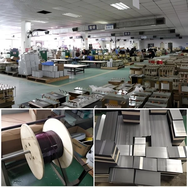
Dufew Electric manufactures the CBU Series as part of its power electronics product portfolio, with production and inspection procedures covering key electrical components, connections, insulation, control functions, and overall product performance.

Depending on the model and application, production and inspection may include electronic component inspection, IGBT component verification, PCB assembly inspection, terminal inspection, insulation testing, electrical function testing, protection function verification, temperature control verification, fault relay testing, and final product inspection.

Product-specific inspection records and technical documents can be provided according to the model and project requirements to support product evaluation and technical verification.

Certification and Standards

The CBU Series is manufactured according to applicable requirements of GB/T 12668.

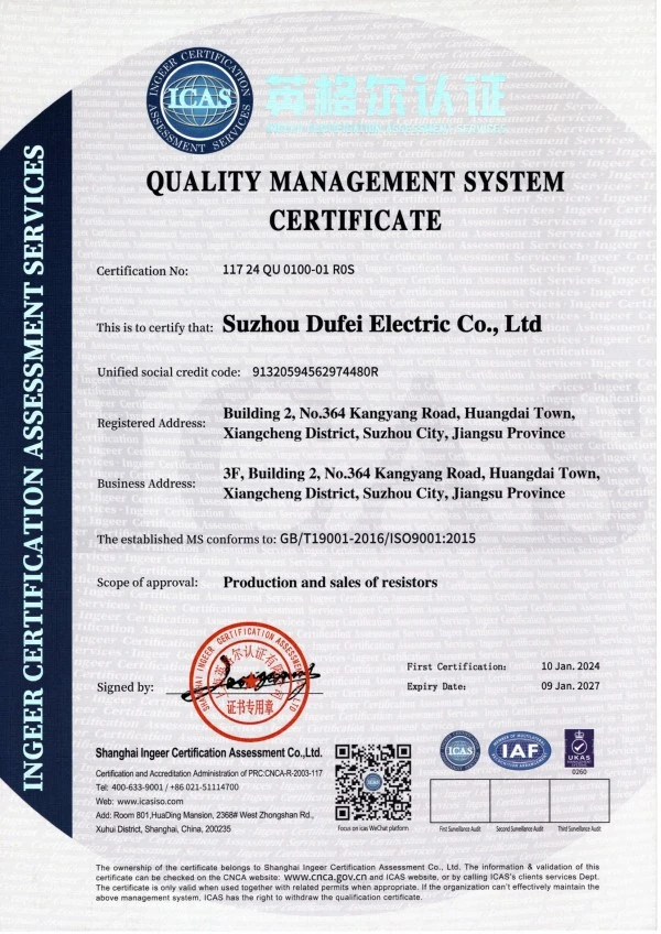
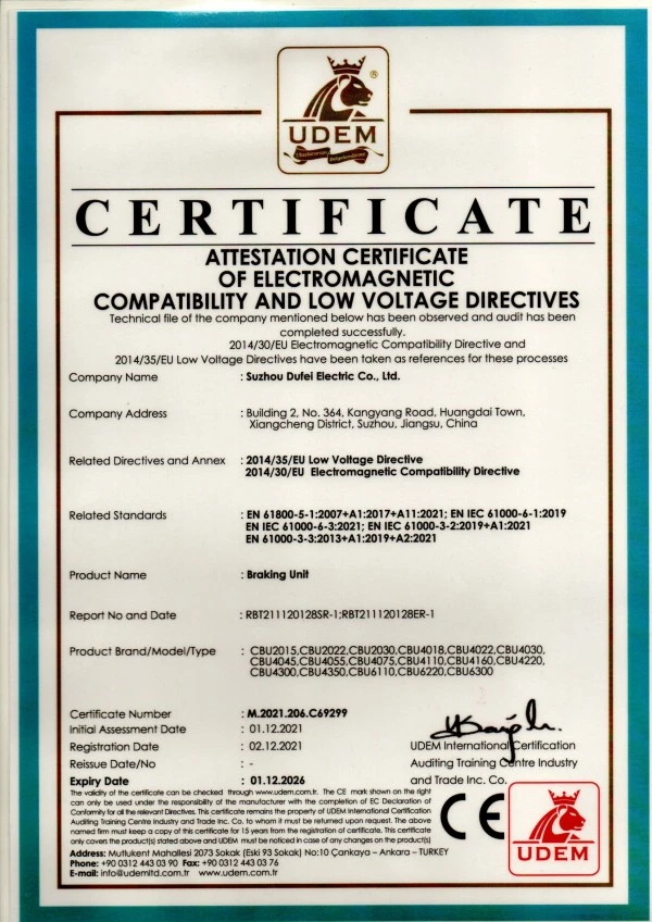
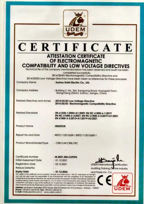
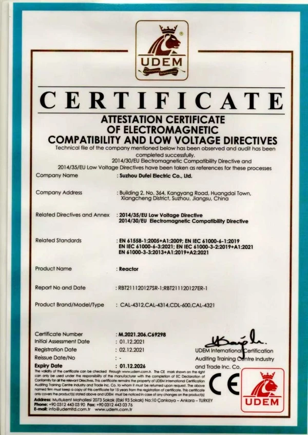
Dufew Electric also holds ISO and CE certifications within its quality and product compliance system. Applicable certificates and technical documents should be confirmed according to the specific product configuration.

Braking ModuleBraking ModuleBraking ModuleBraking Module

Related Power Electronics Components

For applications requiring additional drive-system components, Dufew Electric's product range includes:

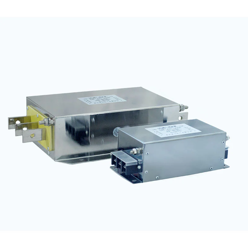
Braking Resistors · Braking Choppers · Braking Modules · Input Reactors · Output Reactors · DC Reactors · EMI Filters · dv/dt Filters · Sine Wave Filters · Harmonic Filters · Transformers · Industrial Resistors

These components cover braking, filtering, reactor and power-control requirements used in industrial drive systems.

Frequently Asked Questions

Q1: What is a Braking Module used for?

A Braking Module controls the transfer of regenerative energy from a VFD's DC bus to an external braking resistor when the bus voltage reaches the configured braking threshold.

Q2: Is it the same as a braking resistor?

No. The module is the switching component, while the resistor converts regenerative electrical energy into heat. They work together as a dynamic braking circuit.

Q3: Where is the unit installed?

It is connected across the VFD DC bus and is normally installed close to the drive when the cabinet layout permits. The connection must follow the product wiring diagram and the drive manufacturer's specifications.

Q4: How should the braking resistor be matched?

The resistance value, power rating, braking energy, braking frequency, and duty cycle should all be considered. The resistor must also be compatible with the DC bus voltage and the selected unit.

Q5: Can multiple CBU units operate in parallel?

Yes. Multiple units can be connected in parallel when additional braking capacity is required. Parallel operation requires appropriate synchronization, DC-bus wiring, resistor configuration, and thermal management.

Q6: Does it require software programming?

The basic braking function operates automatically according to DC-bus voltage and does not normally require software programming. Correct wiring, resistor selection, cooling, and protection connections should be checked before operation.

Q7: Can it be installed inside a VFD cabinet?

Yes. The board-level construction allows cabinet integration, provided that adequate electrical clearance, ventilation, heat dissipation, and installation space are available.

Q8: What information is required for model selection?

Useful information includes the drive voltage, motor power, load type, deceleration time, braking frequency, duty cycle, braking resistor specifications, and installation conditions. These parameters are used to determine the appropriate configuration for the application.

Product Selection

For CBU Series selection, Dufew Electric recommends providing the following information:

Drive model · System voltage · Motor power · Load type · Deceleration time · Braking frequency · Duty cycle · Braking resistor specification · Cabinet installation conditions

The selection should be based on the complete braking system rather than motor power alone. This approach helps determine the appropriate module rating, resistor configuration, parallel arrangement and thermal requirements.

Hot Tags: Braking Module Manufacturer, Supplier, Dynamic Braking Module Wholesale
Send Inquiry
Contact Info
Looking for reliable power electronics components? Contact Dufew Electric, a professional manufacturer and supplier in China, for customized resistors, braking systems, reactors, transformers, and power solutions tailored to your industrial applications.
X
We use cookies to offer you a better browsing experience, analyze site traffic and personalize content. By using this site, you agree to our use of cookies.Privacy Policy