Stay updated with the latest company announcements, technology developments, industry events, and new product releases from Dufew Electric.
Article Summary: A braking chopper is an essential component in dynamic braking systems for variable frequency drives (VFDs), helping manage regenerative energy during motor deceleration and overhauling operation. Dufew Electric provides CBU Series braking choppers designed for compatible 220V, 380V, and 690V drive systems. By monitoring DC bus voltage and switching excess energy to an external braking resistor, these devices help control voltage rise and support reliable braking performance. This guide explains how braking choppers work, their key technical parameters, selection criteria, industrial applications, and installation considerations.
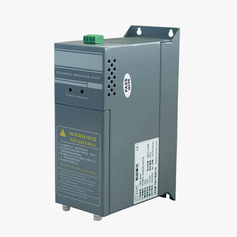
A braking chopper is an electronic switching device used in a variable frequency drive's DC intermediate circuit to manage excess regenerative energy. It works with a braking resistor to help prevent the DC bus voltage from rising beyond an acceptable operating level during motor deceleration.
During normal operation, a VFD supplies electrical energy to a motor to generate mechanical movement. When the motor slows down or drives an overhauling load, it may temporarily operate as a generator. The resulting electrical energy flows back into the DC bus, potentially causing an overvoltage fault if the energy cannot be absorbed adequately.
The braking chopper addresses this issue by switching an electrical path to an external braking resistor when the DC bus voltage reaches a predetermined threshold. The resistor converts the transferred electrical energy into heat.
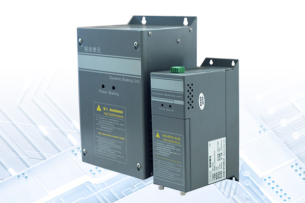
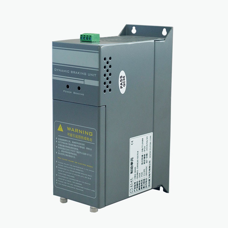
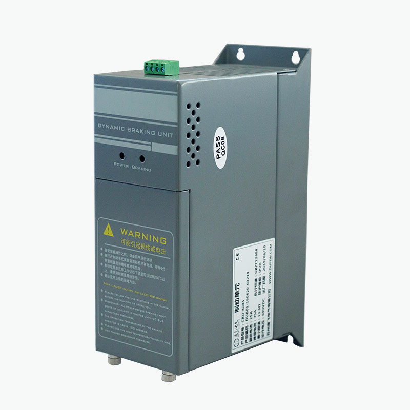
Dufew Electric's CBU Series is designed for external dynamic braking applications in compatible drive systems. Its configuration can be selected according to system voltage, braking requirements, resistor characteristics, and installation conditions.
The operating principle relies on DC bus voltage monitoring and fast electronic switching. In the CBU Series, an IGBT-based switching circuit automatically responds when the voltage reaches the configured braking threshold.
This process repeats as required during braking. It helps control DC bus voltage without requiring a separate external controller for basic voltage monitoring.
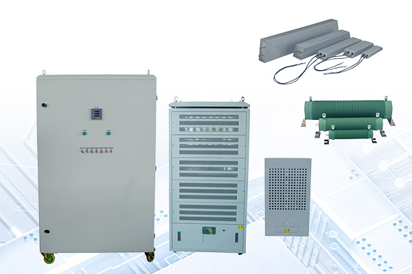
For further information about related equipment, explore Dufew Electric's braking unit solutions and industrial power electronics products.
A properly selected braking chopper can improve the performance of a dynamic braking system, especially in applications involving frequent stops, high inertia, or overhauling loads.
Actual performance depends on the drive, motor inertia, braking resistor, regenerative energy, braking frequency, duty cycle, and installation environment. A chopper should therefore be selected as part of a complete braking system rather than as an isolated component.
Technical specifications determine whether a braking chopper is suitable for a particular VFD installation. The following table summarizes reference parameters published for Dufew Electric's CBU Series.
| Parameter | Reference Specification | Engineering Consideration |
|---|---|---|
| Drive system voltage | 220V, 380V, and 690V AC classes | Must match the compatible drive and DC bus configuration. |
| 220V-class braking voltage | DC 340/360/380/400/420V ±10V | Selectable thresholds for compatible configurations. |
| 380V-class braking voltage | DC 630/660/690/730/760V ±10V | Must be matched to the selected drive and chopper model. |
| 690V-class braking voltage | DC 1140V ±10V | Requires confirmation of system compatibility. |
| Control method | Automatic DC bus voltage monitoring | Enables automatic switching during regenerative operation. |
| Parallel response | ≤1 ms | Reference response specification for compatible parallel configurations. |
| Fan start temperature | Approximately 45°C | Supports thermal management under applicable operating conditions. |
| Overtemperature protection | Approximately 85°C | Provides a thermal protection threshold. |
| Protection rating | IP20 or higher, depending on configuration | Verify the specific model's enclosure rating. |
| Applicable standard | GB/T 12668 | Confirm applicable requirements and documentation for the selected product. |
Note: These are reference specifications, not a guarantee that every model supports every listed setting. Confirm the final model, braking voltage, electrical ratings, and protection functions with the product documentation before ordering or installation.
Selecting a braking chopper requires more than matching its nominal rating to the motor's power. Regenerative energy and thermal loading vary considerably with the driven equipment and operating cycle.
Identify the VFD's rated input voltage and DC bus characteristics. Choose a compatible chopper voltage class and verify that the selected braking threshold suits the drive's permitted operating range.
High-inertia loads can generate significant regenerative energy when decelerated. Shorter stopping times may increase the instantaneous braking power required. Applications such as centrifuges, hoists, and high-speed machinery need particular attention.
The resistor's resistance value, power rating, pulse-energy capacity, and duty cycle must be compatible with the VFD and chopper. An unsuitable resistor can cause excessive current, overheating, or inadequate braking performance.
A machine that stops every few seconds has different thermal requirements from one that stops only occasionally. Frequent braking can increase the average heat generated by the resistor and switching circuit.
Ambient temperature, enclosure ventilation, mounting clearance, and airflow affect thermal performance. The selected equipment must be installed according to the manufacturer's wiring and ventilation requirements.
The following checklist can help prepare a technical inquiry:
Braking choppers are useful in drive systems where a motor returns energy during deceleration, lowering, or other regenerative operating conditions. Typical applications include:
Not every application requires an external braking chopper. The decision depends on the VFD's built-in braking capability, the required stopping time, load characteristics, and the frequency of regenerative operation.
Although these components work together, they perform different functions. Understanding the distinction helps engineers select a compatible dynamic braking system.
| Component | Primary Function | Selection Focus |
|---|---|---|
| Braking chopper | Switches the braking circuit according to DC bus voltage. | Voltage class, switching capacity, protection, and braking requirements. |
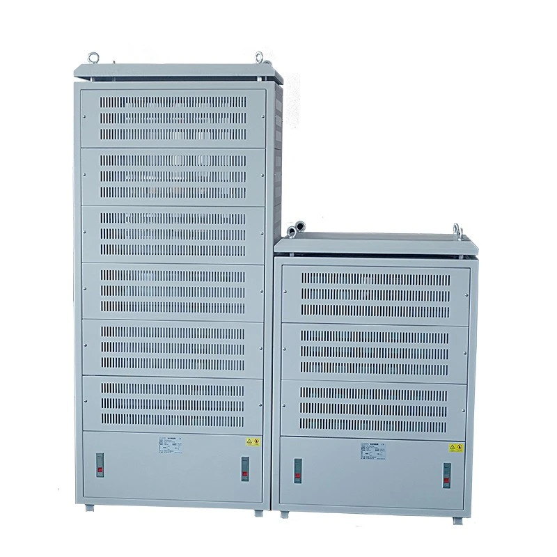
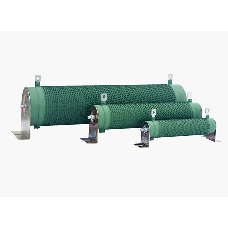
| Braking resistor | Converts regenerated electrical energy into heat. | Resistance, power rating, pulse-energy capacity, and duty cycle. |
| VFD DC bus | Provides the electrical connection to the braking circuit. | Voltage limits, terminal compatibility, and drive specifications. |
A braking chopper cannot dissipate regenerative energy by itself. It controls the switching path, while the resistor absorbs the energy. Both must be compatible with the drive and the intended operating conditions.
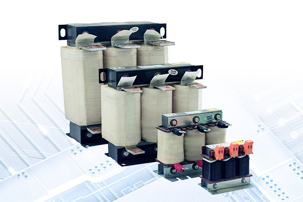
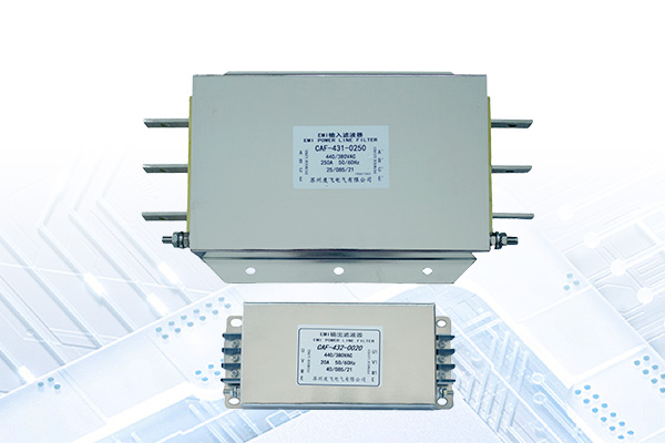
For applications requiring a broader electrical solution, Dufew Electric also offers related power electronics components for industrial drive and power control systems.
Correct installation helps support safe operation, effective cooling, and consistent braking performance. Before commissioning, qualified electrical personnel should verify the following:
During routine maintenance, inspect for loose connections, accumulated dust, restricted airflow, signs of overheating, and abnormal resistor damage. Any testing or maintenance involving the DC bus must follow the manufacturer's safety instructions. The drive should be isolated from its power source, and the DC bus must be verified as discharged before work begins.
Installation and maintenance should comply with applicable electrical safety requirements. Do not rely on the braking chopper as a substitute for a machine's required mechanical or safety-rated braking system.
Its main purpose is to control regenerative energy returned to a VFD's DC bus during deceleration or overhauling operation. It switches excess energy to a compatible braking resistor to help prevent excessive DC bus voltage.
No. The chopper controls when the braking circuit conducts, while the resistor converts electrical energy into heat. They perform complementary functions and must be correctly matched.
No. Some drives have sufficient built-in braking capability for their intended loads. An external chopper may be needed when regenerative energy, braking frequency, or required deceleration exceeds the internal circuit's capability.
The published product information identifies configurations for compatible 220V, 380V, and 690V drive systems. The exact model and braking voltage must be confirmed against the drive's DC bus specifications.
Compatible units can be connected in parallel when a single unit cannot meet the required braking capacity and the product design supports this arrangement. The wiring, resistor configuration, switching coordination, and thermal requirements must be verified for the complete system.
Selection depends on the drive's resistance limits, braking power, energy per braking cycle, frequency of operation, and duty cycle. The resistor must also be compatible with the chopper's electrical ratings and installation conditions.
Provide the VFD model, system voltage, motor power, load type, deceleration time, braking frequency, resistor specifications, duty cycle, and installation conditions. These details help the supplier assess the appropriate model and configuration.
A properly selected braking chopper helps manage regenerative energy, control DC bus voltage rise, and support reliable dynamic braking in industrial drive systems. Its effectiveness depends on matching the chopper, braking resistor, drive voltage, load characteristics, and thermal requirements to the application.
Dufew Electric's CBU Series provides braking chopper options for compatible 220V, 380V, and 690V drive systems, with model selection based on electrical ratings and operating conditions. Whether your project involves elevators, cranes, conveyors, centrifuges, or other industrial machinery, careful specification review is essential for a suitable braking solution.
If you are looking for a reliable braking chopper manufacturer and supplier for your industrial drive project, explore Dufew Electric's braking chopper products and contact us with your drive specifications, braking requirements, and installation details. Our team can help you evaluate a suitable configuration for your application.