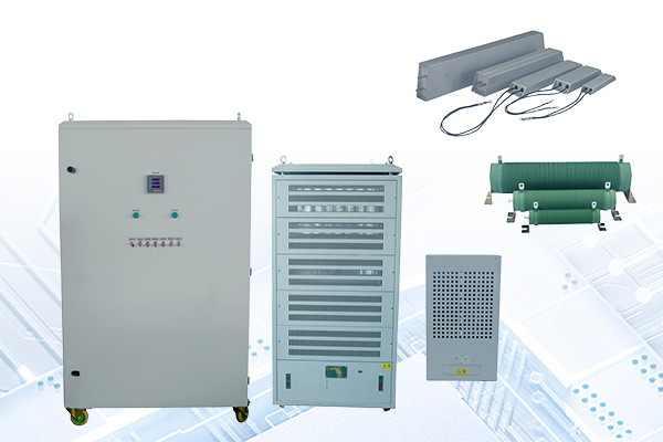
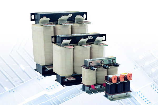
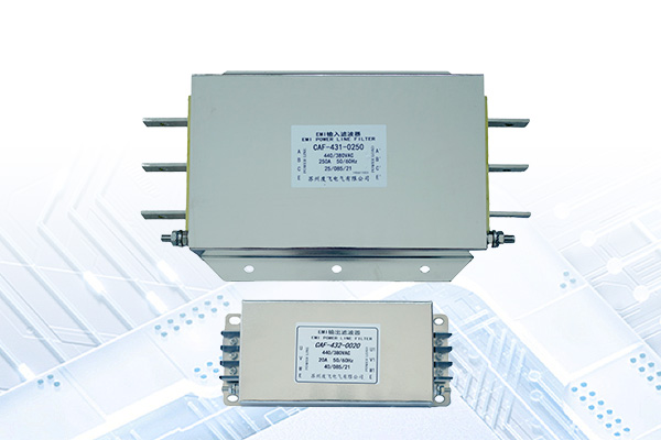
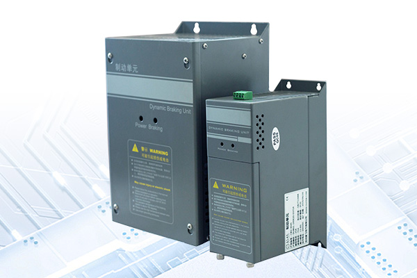
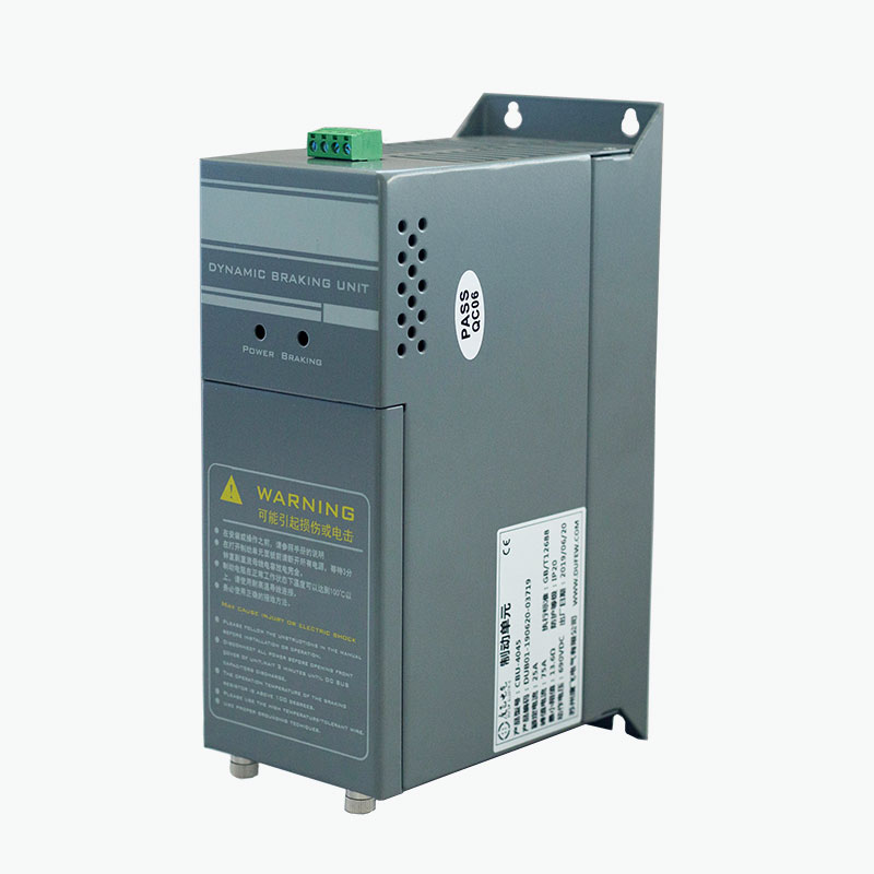
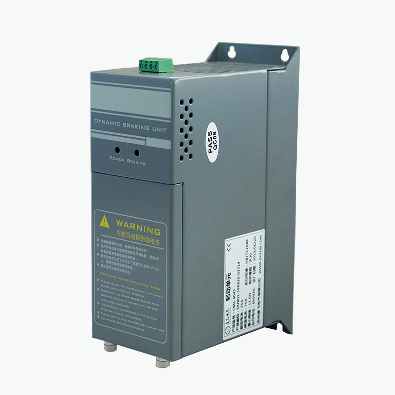
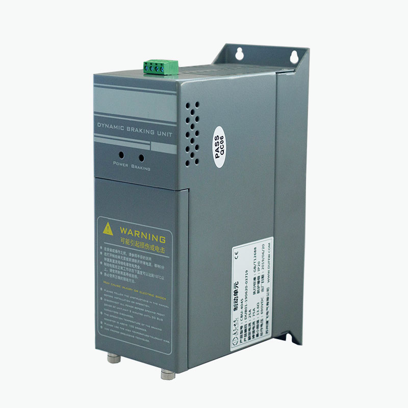
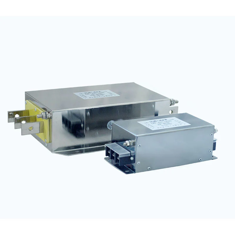
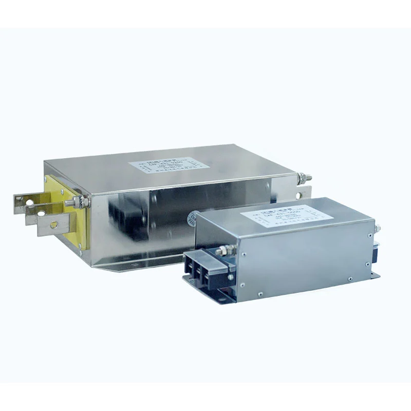
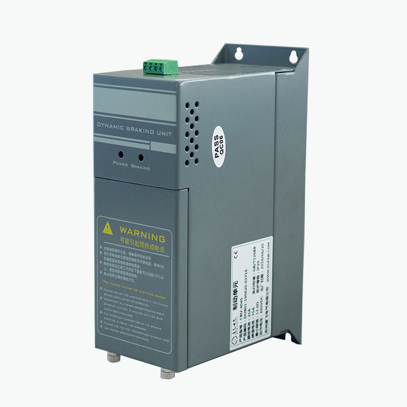
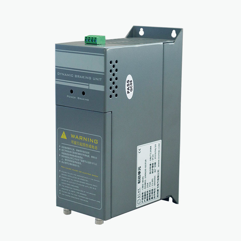
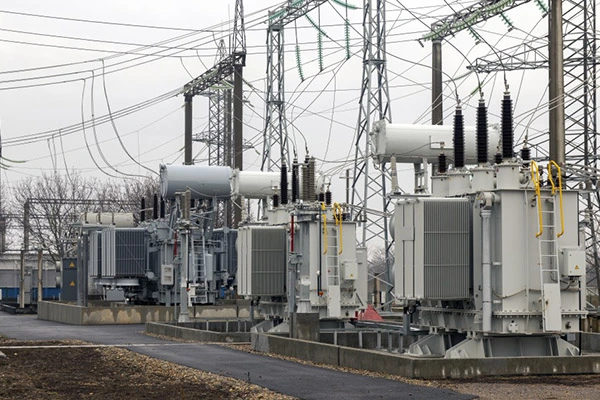
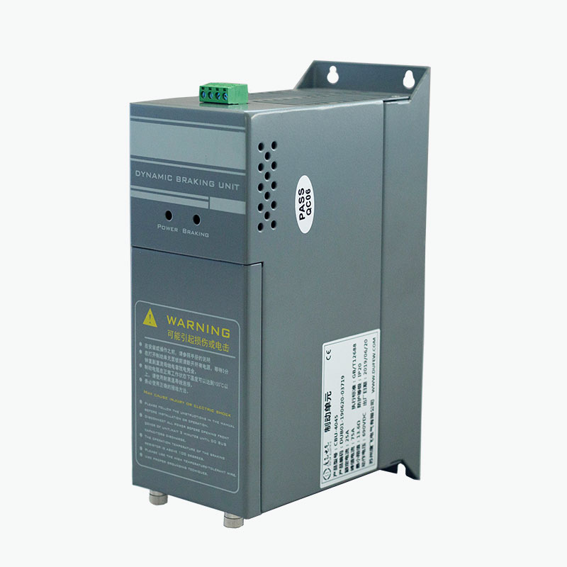
We offer a comprehensive portfolio including resistors, braking units, reactors, power filters, and transformers, with full customization options to meet diverse application requirements.
Dufew Electric Energy Regeneration Unit is an active energy recovery system for variable frequency drive applications with frequent or sustained regenerative operation. It converts regenerative DC energy from the VFD DC bus into AC power synchronized with the utility grid, allowing recovered energy to be returned to the electrical supply instead of being dissipated through a braking resistor. The system uses IGBT-based PWM control and sinusoidal current tracking, with a reported regeneration efficiency of over 97% and current THD below 5% under specified operating conditions.
During normal operation, a VFD supplies electrical energy to the motor. When the motor decelerates, a high-inertia load slows down, or a suspended load moves downward, mechanical energy can flow back through the motor and VFD to the DC bus.
This regenerative energy increases the DC-bus voltage.
There are two common ways to handle this energy:
- Dynamic braking: transfers the energy to a braking resistor, where it is dissipated as heat.
- Active regeneration: converts the DC energy into synchronized AC power and returns it to the electrical supply.
The basic energy path is:
Motor → VFD → DC Bus → Regeneration Unit → AC Grid
This configuration is intended for applications where regenerative energy occurs frequently or for relatively long periods and where recovering the energy is technically or economically preferable to dissipating it as heat.
The system operates on the DC side of the VFD and uses an active inverter to transfer regenerative energy back to the AC supply.
During regenerative operation:
Mechanical Energy → Motor → VFD DC Bus → IGBT PWM Inverter → AC Grid
The process can be summarized as follows:
1. The motor enters a regenerative condition during deceleration or overhauling operation.
2. Regenerated electrical energy flows back to the VFD DC bus.
3. The DC-bus voltage rises as regenerative energy accumulates.
4. The active inverter detects the operating condition and begins energy conversion.
5. IGBT switching converts the DC energy into controlled AC current.
6. The output is synchronized with the utility supply for grid-side energy transfer.
7. The recovered energy is returned to the electrical system instead of being dissipated primarily through a braking resistor.
Unlike a conventional braking chopper, the unit does not use a resistor as the main energy-dissipation path.
The appropriate solution depends on the actual regenerative energy and operating cycle.
| Comparison | Active Energy Regeneration | Braking Module + Resistor |
|---|---|---|
| Energy handling | Returns regenerated energy to the AC supply | Converts regenerated energy into heat |
| Main application | Frequent or sustained regeneration | Short or intermittent braking |
| Resistor required | Not used as the primary energy path | Required |
| Heat generated by braking | Lower resistor-related heat load | Regenerative energy is dissipated as heat |
| Energy utilization | Recovered for use by the electrical system | Not recovered |
| System configuration | Active inverter and grid-side connection | Braking module and resistor |
| Key selection factor | Regenerative power and operating profile | Braking power, resistance and duty cycle |
| Typical consideration | Energy recovery and reduction of braking heat | Simpler dynamic braking for intermittent events |
Neither solution is suitable for every application. For short and infrequent braking events, a resistor-based braking system may be sufficient. Applications with frequent or sustained regeneration require evaluation of the recoverable energy, regenerative power and operating cycle.
The unit converts regenerative DC energy from the VFD DC bus into AC power and returns the recovered energy to the electrical supply instead of dissipating it through a braking resistor.
The system transfers recovered energy to the AC supply according to the grid's voltage, frequency and phase conditions, providing a controlled path for regenerative power.
The unit responds to DC-bus voltage changes during regenerative operation and controls the energy recovery process according to the configured operating conditions.
Because regenerative energy is recovered rather than primarily dissipated through a braking resistor, the system can reduce the heat generated by resistor-based braking in applications with frequent or sustained regeneration.
Multiple units can be configured in parallel where additional regeneration capacity is required and the selected models support parallel operation.
The system provides protection and fault monitoring for abnormal electrical and thermal conditions, with the applicable functions determined by the selected model.
The power conversion stage uses IGBT switching devices and PWM control to convert regenerative DC energy into controlled AC current for grid-side energy recovery.
The inverter uses sinusoidal current tracking to regulate the feedback current. The supplied product specification indicates current THD below 5% under specified operating conditions.
The system monitors the VFD DC bus and responds to voltage changes associated with regenerative operation. The actual operating threshold depends on the system voltage and selected configuration.
The inverter uses the AC supply as its reference for voltage, frequency and phase conditions. The system also supports automatic phase-sequence identification according to the product configuration.
An integrated reactor and filtering components help manage inverter switching current and reduce high-frequency interference during energy conversion.
For applications requiring higher regeneration capacity, supported units can operate in parallel with coordinated control. The supplied product information specifies a synchronization response of ≤1 ms for applicable parallel configurations.
Protection functions can include DC-bus overvoltage, AC-side overcurrent, short circuit, over-temperature, grid undervoltage and phase-related faults. The exact protection functions should be confirmed against the selected model's technical documentation.
| Application | Regenerative Condition | Why Energy Recovery May Be Considered |
|---|---|---|
| Elevators | Repeated acceleration, deceleration and load movement | Frequent regeneration over operating cycles |
| Hoists & Cranes | Lowering suspended loads | Potential energy is returned to the DC bus |
| Mine Hoists | Repeated lifting and lowering | Long-duration regenerative operation may occur |
| Centrifuges | High-inertia deceleration | Rotational energy is released during braking |
| Test Benches | Repeated motor acceleration/deceleration | Regenerative operation can occur frequently |
| Machine Tools | Rapid spindle deceleration | Short braking cycles may generate regeneration |
| Textile Machinery | Repeated speed changes | Regenerative events may occur throughout the cycle |
| Oilfield Equipment | Repetitive mechanical movement | Operating cycles may produce recurring regeneration |
| Other Overhauling Loads | Load drives the motor during part of the cycle | Continuous or repeated energy return to the DC bus |
Note: Application suitability should be evaluated from actual regenerative power and duty cycle rather than the motor's rated power alone.


An active regeneration system may be worth evaluating when:
- Regenerative operation occurs frequently.
- The load remains in an overhauling condition for extended periods.
- A high-inertia load is repeatedly accelerated and decelerated.
- A conventional braking resistor would generate substantial heat.
- The installation has limited heat-dissipation capacity.
- The recovered energy is significant relative to the system's operating requirements.
- Energy recovery is part of the project's energy-management objectives.
For occasional short-duration braking, a conventional braking module and resistor may provide a simpler configuration.
The following information represents the currently available product data. Final values should be confirmed against the selected model and project specification.
| Parameter | Specification / Selection Basis |
|---|---|
| Conversion Method | IGBT-based PWM active inverter |
| Grid Connection | AC utility supply |
| System Voltage | Available according to the selected configuration |
| Energy Conversion | Regenerative DC energy to synchronized AC power |
| Regeneration Efficiency | >97% under specified operating conditions |
| Current THD | <5% under specified operating conditions |
| Grid Synchronization | Voltage, frequency and phase tracking |
| Phase Sequence | Automatic identification according to configuration |
| Filtering | Integrated reactor and noise filtering |
| Cooling | According to selected model |
| Protection | Overvoltage, overcurrent, short circuit, overtemperature and applicable grid protection |
| Parallel Operation | Available according to system configuration |
| Installation | VFD cabinet or designated electrical enclosure |
| Applicable Standard | GB/T 12668, where applicable |
Note: The available technical information for this product does not provide a complete model-specific rated-power table. Regeneration capacity, rated current, grid voltage, cooling requirements and other electrical parameters should therefore be confirmed from the applicable product datasheet before selection.
| Parameter | What to Provide | Why It Matters |
|---|---|---|
| VFD Model | Manufacturer and complete model number | Confirms DC-bus configuration and electrical compatibility |
| System Voltage | 220 V / 380 V / 690 V or applicable voltage | Determines the required electrical configuration |
| Motor Power | Rated motor output | Provides a starting reference for system sizing |
| Regenerative Power | Peak and/or continuous regenerative power | Determines required recovery capacity |
| Load Type | Hoisting, high-inertia, overhauling, test bench, etc. | Defines the energy-generation pattern |
| Deceleration Time | Required stopping time | Helps determine peak regenerative power |
| Regeneration Frequency | Events per hour, cycle or shift | Determines operating and thermal requirements |
| Regeneration Duration | Duration of each regenerative event | Important for continuous-duty sizing |
| DC-Bus Voltage | Normal and maximum operating voltage | Confirms compatibility with the conversion stage |
| Grid Conditions | Voltage, frequency and phase configuration | Required for grid-side synchronization |
| Existing Braking System | Braking unit/resistor information | Helps determine whether an existing braking circuit can be replaced or integrated |
| Installation Conditions | Cabinet space, cooling and ambient temperature | Determines installation and thermal requirements |
| Parallel Requirement | Required regeneration capacity | Determines whether multiple units are necessary |
The regeneration unit is connected between the VFD DC bus and the AC grid-side regeneration circuit according to the manufacturer's wiring diagram.
Before installation:
1. Confirm the VFD DC-bus voltage is within the specified operating range.
2. Confirm the AC grid voltage and frequency are compatible with the regeneration unit.
3. Check the required regeneration power and duty cycle.
4. Provide adequate cabinet ventilation and clearance around heat-generating components.
5. Use appropriately rated cables, protection devices and terminals.
6. Verify grounding and protective connections.
7. Confirm the grid-side connection and phase-sequence requirements.
8. Complete electrical inspection before energizing the system.
For retrofit projects, the existing VFD model, DC-bus configuration and braking arrangement should be reviewed before selecting the regeneration unit.
Dufew Electric manufactures power electronics components for industrial drive and power-control applications, with production and inspection procedures covering key electrical, functional, and safety-related requirements.
For an energy regeneration unit, the applicable procedures may include IGBT and power-component inspection, PCB assembly inspection, electrical connection inspection, insulation testing, functional testing, protection-function verification, temperature-control verification, grid-side operation testing, and final product inspection.
Model-specific test records and technical documents can be provided according to project requirements, supporting product evaluation, system integration, and quality verification.
The supplied product information indicates compliance with GB/T 12668 where applicable.
Dufew Electric also maintains ISO and CE-related quality and product compliance documentation. Applicable certificates and conformity documents should be confirmed according to the specific product model, configuration and destination market.


It converts regenerative energy from a VFD DC bus into AC power that can be returned to the utility grid. It is mainly considered for applications with frequent, high-power or sustained regenerative operation.
Dynamic braking sends regenerative energy to a resistor, where it is converted into heat. Energy regeneration converts the DC energy into synchronized AC power and returns it to the electrical system.
In a properly designed regeneration system, the regeneration unit can replace the resistor-based energy dissipation path. However, the existing VFD, DC-bus configuration, protection system and application duty must be checked before making the change.
Not automatically. Compatibility depends on the VFD's DC-bus voltage, power configuration, electrical interface, load characteristics and the regeneration unit's grid-side requirements. The specific VFD model should be provided for selection.
Parallel operation can be used when additional regeneration capacity is required, provided that the selected models support parallel operation and the DC-bus, AC-side connection, synchronization and thermal conditions are correctly designed.
It can reduce the heat generated by regenerative braking because the recovered energy is transferred back to the electrical system rather than being dissipated entirely through a resistor. The regeneration unit itself still produces electrical and switching losses and therefore requires appropriate cooling.
The key information includes system voltage, VFD model, motor power, load type, regenerative power, deceleration time, regeneration frequency, regeneration duration, DC-bus voltage and installation conditions.
The supplied product specification states a regeneration efficiency of 97% or higher. The actual efficiency depends on the operating point, load, power level and system configuration, so the applicable test conditions should be confirmed from the model-specific technical documentation.
For technical evaluation, provide:
VFD model · System voltage · Motor power · Load type · Regenerative power · Deceleration time · Regeneration frequency · Regeneration duration · DC-bus voltage · Grid conditions · Installation environment
Dufew Electric can then determine whether an energy regeneration system is appropriate and identify the required configuration.
Address
No. 364, Kangyang Road, Huangdai Town, Xiangcheng District, Suzhou City, Jiangsu Province, China
Tel